RezaFarrokhi
Aerospace
- Aug 15, 2018
- 7
Hello Dear friends,
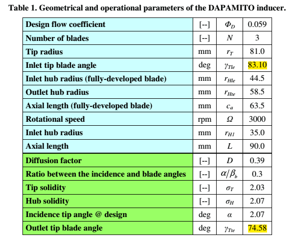
I want to draw an inducer that is placed in the inlet of a high-speed centrifugal pump using the geometric parameters that I obtained from an experimental work of the century paper.
I want to do this using CAD softwares such as Solidworks or CATIA.
But, I don't know how to apply parameters like Solidity, Inlet Blade Angle, Outlet Blade Angle, Diffusion factor mentioned in the article to drawing this geometry.
I would be grateful if you could guide me.
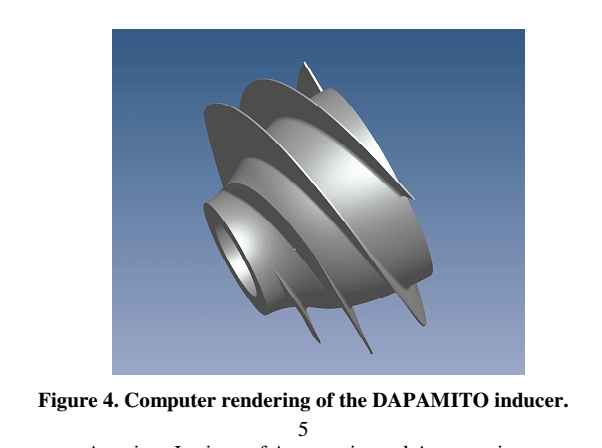
I have attached a table of specifications and an overview of the geometry to be obtained.
Best Regards,
Reza
I want to draw an inducer that is placed in the inlet of a high-speed centrifugal pump using the geometric parameters that I obtained from an experimental work of the century paper.
I want to do this using CAD softwares such as Solidworks or CATIA.
But, I don't know how to apply parameters like Solidity, Inlet Blade Angle, Outlet Blade Angle, Diffusion factor mentioned in the article to drawing this geometry.
I would be grateful if you could guide me.
I have attached a table of specifications and an overview of the geometry to be obtained.
Best Regards,
Reza