Continue to Site

Eng-Tips is the largest engineering community on the Internet

Intelligent Work Forums for Engineering Professionals

  • Congratulations 3DDave on being selected by the Eng-Tips community for having the most helpful posts in the forums last week. Way to Go!

Cantilevered Beam on Wall 1

Zoobie777

Chemical
Jun 28, 2022
45
Hey,

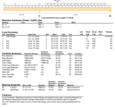
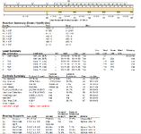
I come across the situation often enough and I want to know if I'm designing things right or if I am cheating. I use iStruct but I imagine other software is similar. When I put a beam in line with a wall with a cantilever I can only get the beam to pass if there are two bearings. I get the beam to work by creating a gap between the walls at the corner where the cantilever starts. This is usually an inch or two. For example if I had a cantilever of 2 ft extending out from the wall, the beam analysis would show 2ft unsupported, 5.5" bearing, 2" gap, 6' of bearing. Is this OK? I can't think of anything else. In reality the beam would be sitting on the very top plate and there would likely be a stud pack at the corner.

If the gap is too small, I get a shear failure on the wall bearing. If I increase the gap by an inch or two, the shear goes away. How (in real life) would I have to install the beam? Is there something else I should be doing to analyze this correctly?

In the example below, the second output that fails shows the same size bearing length on the diagram but B2 but its actually 2" longer (2" closer to B1).

Thanks,
1749760594929.png

1749760686771.png
 
Replies continue below

Recommended for you

I'm struggling to interpret what is going on here as the diagram sucks and I'm not familiar with the analysis software
Where are the connections to the top plate defined to resolve the cantilever loads?

So, some general thoughts

1/ It looks like you've applied 2 loads on the backspan and 1 on the cantilever?
This is usually not the right way to do it - usually you'd design for G everywhere and only apply Q to the cantilever to get the worst case 2

2/ - You have to be very careful with cantilevers with continuous backspan supports
You have little control over where your builder actually puts the fixings that you specify, and the layman thinks that adding a few more cleats is better
However, the closer together they are, the higher the loads are due to the reduced lever arm to resolve the cantilever moment
And stiffer beam = people feel more comfortable loading it = higher loads on top of your higher loads = higher chance of failure
This is a famous engineering failure here - one of the many issues were continuous bearers that had been designed assuming support at the front and the back pile, ignoring that they were also cleated to the intermediate piles, leading to overloading of the connections
 
Best case the if you provide a single tie down at the far end of the cont. wall support it will tend to act like a propped cantilever for determination of the forces on the wall studs.

As @Greenalleycat noted if they get overzealous and start fastening it for uplift resistance at ever stud the reactions change.

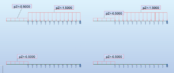
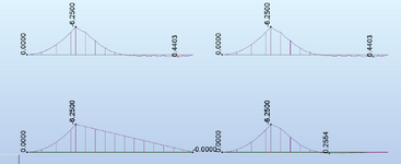
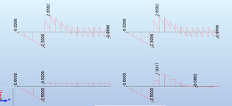
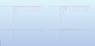
In the below images:
Left top - compression only springs through the backspan with a compression/tension spring at the far end, cantilever and backspan loaded
Left bottom - compression only springs through the backspan with a compression/tension spring at the far end, cantilever loaded
Right top - compression/tension springs, cantilever and backspan loaded
Right bottom - compression/tension springs, cantilever loaded

springs are at 12" o.c. and set to K = AE/L for a 10ft tall 2x6 SPF No2 stud

1749762872851.png

Moment:
1749762917833.png

Shear:
1749762941526.png

Reactions:

1749763086812.png
 
Yeah, this is an awkward thing. That said, it's ubiquitous in residential, multi-unit construction and I've yet to see it cause a problem. Most folks in my market just design the cantilever bit and disregard the rest, for better or worse. And my market is your market.

Quite often this condition will also arise where the back span is poorly braced against rollover. That's the version of this that rattles me the most.

A good theoretical discussion of this, applied to shear wall buildings, can be found here. As with that situation, you change some of your distributed, rigid supports to springs and things get better fast. But it's hard to know what the stiffness of such springs ought to be and there's just no way that you can get away with that level of detailed analysis in light frame residential design.
 
I'm struggling to interpret what is going on here as the diagram sucks and I'm not familiar with the analysis software
Where are the connections to the top plate defined to resolve the cantilever loads?

So, some general thoughts

1/ It looks like you've applied 2 loads on the backspan and 1 on the cantilever?
This is usually not the right way to do it - usually you'd design for G everywhere and only apply Q to the cantilever to get the worst case 2

2/ - You have to be very careful with cantilevers with continuous backspan supports
You have little control over where your builder actually puts the fixings that you specify, and the layman thinks that adding a few more cleats is better
However, the closer together they are, the higher the loads are due to the reduced lever arm to resolve the cantilever moment
And stiffer beam = people feel more comfortable loading it = higher loads on top of your higher loads = higher chance of failure
This is a famous engineering failure here - one of the many issues were continuous bearers that had been designed assuming support at the front and the back pile, ignoring that they were also cleated to the intermediate piles, leading to overloading of the connections
Hey,

To clarify the loads:

Load 0 is the self weight across the whole span. On the cantilever are point loads from the roof joists above (loads 2, 3, 4 & 5). In reality the joists continue over the entire span (24"oc) but the software is showing it as a linear load (load 1). To simplify, point loads of ~120 lbf dead load & ~450 lbf snow load at intervals of 2' starting at end of cantilever.
Thanks, that helped
I think my point 1/ is relevant then - be careful with assuming that loads are equal on the backspan and the cantilever
Otherwise you will underestimate the deflection and the hold down forces at the backspan
Also, should there be a live load component to this? If you have joists then presumably someone can walk on them?
 
I typically design these as a propped cantilever and then I will strap it down to each stud to prevent the theoretical crack that may form at the top of the wall.
Like KootK, I have yet to see this as an issue in practice.
 
Thanks, that helped
I think my point 1/ is relevant then - be careful with assuming that loads are equal on the backspan and the cantilever
Otherwise you will underestimate the deflection and the hold down forces at the backspan
Also, should there be a live load component to this? If you have joists then presumably someone can walk on them?
Roof joists. Just snow and DL.
 
It is basically is calculating a very short back span aka your gap which isn’t really realistic.
 
Ah OK. We'd call those purlins supported by rafters typically, or maybe rafters supported on a roof beam depending on the exact roof framing setup
Makes sense now and I understand your problem better.

Looks like classic misuse of software: rubbish in, rubbish out

Back calculating, your first case is fully resolving the moment of 9954 ft-lbs over the 5.5" wide plate + 2" dummy tolerance you put in + some arbitrary 0.25" gap?
= 7.75" lever arm
I don't know which way your 6" length x 5.25" width is defined in the model - maybe it's 5.25" + an allowance for 0.25" bearing either side? - but that's not hugely important

In the second case, you removed your dummy 2" gap so it resolved over 5.75"
This is a tiny lever arm to resolve the moment so it's giving you a huge force to resolve the moment, leading to a large shear
Is this realistic? Are you expecting that you will put a large tie down immediately at the end of the parallel wall?
Or is it just that the model isn't smart enough to know better and assumes perfect restraint as soon as the beam touches the parallel wall line

This is a candidate for the issue I highlighted with the Cave Creek example
 
Roof joists. Just snow and DL.
BTW, I hate the term. It is technically incorrect, especially if its sloped (I believe). The material used is an i-joist so I guess it is now in the vernacular. My bigger pet peeve is the use of the terms jack stud, trimmer, and cripple, with cripple being the most inaccurate IMHO.:ROFLMAO:
 
Ah OK. We'd call those purlins supported by rafters typically, or maybe rafters supported on a roof beam depending on the exact roof framing setup
Makes sense now and I understand your problem better.

Looks like classic misuse of software: rubbish in, rubbish out

Back calculating, your first case is fully resolving the moment of 9954 ft-lbs over the 5.5" wide plate + 2" dummy tolerance you put in + some arbitrary 0.25" gap?
= 7.75" lever arm
I don't know which way your 6" length x 5.25" width is defined in the model - maybe it's 5.25" + an allowance for 0.25" bearing either side? - but that's not hugely important

In the second case, you removed your dummy 2" gap so it resolved over 5.75"
This is a tiny lever arm to resolve the moment so it's giving you a huge force to resolve the moment, leading to a large shear
Is this realistic? Are you expecting that you will put a large tie down immediately at the end of the parallel wall?
Or is it just that the model isn't smart enough to know better and assumes perfect restraint as soon as the beam touches the parallel wall line

This is a candidate for the issue I highlighted with the Cave Creek exam
To clarify, the software automatically changes the bearing width to the beam width. In this case a 3-ply LVL (1.75" x 3 = 5.25"). I suggest that the software isn't smart enough. Wouldn't use it to build a bridge (which it couldn't do anyways), but works good enough for a wood frame house in Canada.
 
Reading your outputs (and forgive me for errors as I don't work in imperial)
Moment = 9954 ft-lbs
Shear = 15408 lbs or 20771 lbs

9954/15408 = 0.646ft = 7.75"
9954/20771 = 0.479ft = 5.75"

So in neither case is it 5.25" - there's a mystery 0.5" being applied once correcting for your 2" dummy gap

Regardless, it is not the software that isn't smart enough: you're the one designing this
You tell us, is this lever arm realistic for how you will tie these rafters down?
If you are strapping it to the first stud then the software is plenty smart enough and your proposed design is failing
If you are not strapping it down to the first stud then you have not set your model up correctly - which isn't the model's fault
 
Trying to sort out the reality of what's happening and the fiction from the software. Another question I have is what is the real load on bearing 1. My first example above shows a factored load of 18000 lbs. If I model the beam as per below its only 5700 lbs. My guess it will depend on how it is restrained along its length.

1749771313402.png

Thanks. You guys are always great help!
 
Trying to sort out the reality of what's happening and the fiction from the software. Another question I have is what is the real load on bearing 1. My first example above shows a factored load of 18000 lbs. If I model the beam as per below its only 5700 lbs. My guess it will depend on how it is restrained along its length.


Thanks. You guys are always great help!
This is what all of us have been saying in this thread
The bearing point is known as it will sit on the LVL beams at the front
The unknown is where the tension restraint is that resolves the cantilever moment further back

As the designer, you can specify this: closer together = lower deflection of beam (good) but higher tie down force (harder to design for)
It's a balance of what you can make work as a realistic tie down while keeping an acceptable deflection at the tip of the beam

However, you then need to think closely about what will actually be done on site
As I said at the start, the layman thinks that more fixings = better
There's a decent chance you turn up to find that they have completely ignored your design and have put in far more fixings
This will reduce the lever arm and increase your forces - which could be problematic
 
Has Celt been adding new features to his calculator?
I wish…floating license for Autodesk Robot these threads give me some nice test cases to run.
Trying to sort out the reality of what's happening and the fiction from the software. Another question I have is what is the real load on bearing 1. My first example above shows a factored load of 18000 lbs. If I model the beam as per below its only 5700 lbs. My guess it will depend on how it is restrained along its length.

View attachment 10748

Thanks. You guys are always great help!
the difference boils down to the effective moment arm for the cantilever moment between the two supports.
 
This is what all of us have been saying in this thread
The bearing point is known as it will sit on the LVL beams at the front
The unknown is where the tension restraint is that resolves the cantilever moment further back

As the designer, you can specify this: closer together = lower deflection of beam (good) but higher tie down force (harder to design for)
It's a balance of what you can make work as a realistic tie down while keeping an acceptable deflection at the tip of the beam

However, you then need to think closely about what will actually be done on site
As I said at the start, the layman thinks that more fixings = better
There's a decent chance you turn up to find that they have completely ignored your design and have put in far more fixings
This will reduce the lever arm and increase your forces - which could be problematic
Thanks, my thick head is getting it.
 
In a sort of related question, maybe for KootK as this applies to Canadian residential construction, what is the best/normal way to install this beam? Placed on top of the very top plate (in this case wall framed 9.5" lower) or built into the wall?
 
Taking into consideration that I am a thick-headed chemical engineer and that the software at my disposal does not allow for straps, springs, pinned vs roller bearings, nails, screws, duct tape or anything else of the sort, would this be the best representation of what would happen if I strapped the beam at each stud assuming 24" oc (which is the norm for exterior walls where I am from).

1749773556092.png
 

Part and Inventory Search

Sponsor