Continue to Site

Eng-Tips is the largest engineering community on the Internet

Intelligent Work Forums for Engineering Professionals

  • Congratulations waross on being selected by the Eng-Tips community for having the most helpful posts in the forums last week. Way to Go!

Calculate required circuit capacity based on inrush and typical current specs 5

Status
Not open for further replies.

PaulKraemer

Electrical
Jan 13, 2012
155
Hi,

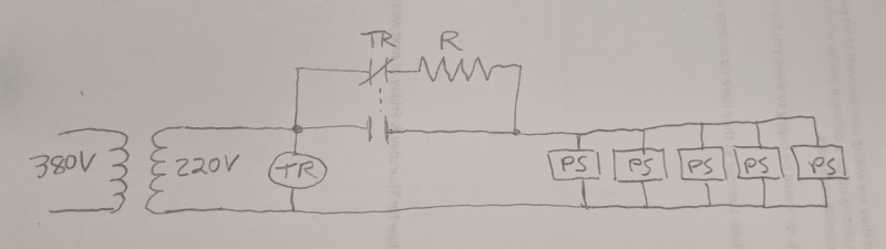
I am going to be installing five components for which the power specifications are listed as follows:

1.2 amps @ 230 VAC typical
Inrush current 40A @ 230 VAC (cold start)

... I am trying to determine the lowest rated circuit that I can safely use to power all five components, assuming that they will all receive power at the same time. My gut feeling (having used these components before) is that a circuit fused at 10 amps would allow me to power all five components simultaneously without blowing the fuse (although I do not currently have the components on hand to verify this).

I have never really understood how to factor inrush current specifications (in addition to "typical" current specifications) into calculations to determine my required circuit capacity.

If anyone here can give me a clue how to do this, I would greatly appreciate it.

Thanks and best regards,
Paul
 
Replies continue below

Recommended for you

Do you know the duration of the inrush? I would say it depends on the time-current-characteristic of the overcurrent protective device protecting the circuit.

Mike
 
Inrush:
Induction Motors; 600%
Incandescent lighting; 1000%
Transformers; 2500%
Capacitors; It depends, (Depending on the resistance in the charging circuit it may be very high.)
Compare your inrush curve with the time/current curve of the breaker or fuses.
You may need two levels of protection.
Over current- Short circuit protection.
Overload protection:- Steady state current.
One method is to select a fuse (Probably a dual element fuse) or a thermal magnetic breaker that will take the inrush and size you conductors to be protected by the lower continuous rating of the device.
Example: A 15 Amp thermal magnetic breaker will trip on over 15 Amps continuous but will trip instantly on 150 amps.
I'll let you do the research to find a suitable device for your project.

Bill
--------------------
"Why not the best?"
Jimmy Carter
 
Hi waross, mparenteau, and IRstuff -

Thank you for your responses. To answer IRStuff's question, the "Inrush Current 40A @ 230 VAC (cold start)" spec is per component. Based the info provided by waross (Induction Motors 600%; Incandescent lighting 1000%; Transformers 2500%), I think the inrush spec is starting to make sense to me.

The standard version of this component works on 24 VDC. When powered by 24 VDC, the specs say "24 VDC +/- 10%, 0.6 amps typical, 2.2 amps internal fusing (resetting thermal fuse)".

Optionally, you can buy this component configured for an AC supply voltage (either 115 VAC or 230 VAC). I know that the AC version is the same exact component. Internally, it works on 24 VDC. They just add a power supply that takes the incoming AC voltage and converts it to 24 VDC. I suspect that it is this power supply that causes the inrush rather than the component itself.

When I posted my original question, I did my best to simplify my situation for the purpose of clarity. The reason that I want (or have to) figure out the lowest rated circuit that will be required to power five of these components is because I will have to install them on a machine that already exists. This machine has 230 VAC single phase fused at 30 amps. This power source is used to power other components that are already installed on this machine. I'm trying to figure out if I can add my five components to this same 230 VAC (30 amp) supply circuit without being afraid of blowing the 30 amp fuses.

Looking at how the existing components are fused, I am certain this 230 VAC 30 amp circuit has enough excess capacity to handle the "typical" current of my five new components. I am now just concerned about the inrush.

I suppose the questions I will have to ask are:

(1) from the component supplier - what is the expected duration of the inrush
(2) what is the time-current-characteristic of the fuses that protect the circuit

It might be difficult for me to get an answer to #2 because this machine is in Greece and I am in New Jersey. Also, the machine was built in 1991, so I expect that the fuses are of a type that were typical of what was sold at that time. I find it is sometimes difficult to find information on such old equipment.

If I can't get answers that make me comfortable that this will work, I might just have to request a new, dedicated circuit for the new components. Either that, or consider buying the 24 VDC version of these components and adding a new 24 VDC power supply to power them. (In the hope that the inrush current of a single 24 VDC power supply would be less than five separate 24 VDC power supplies)

Thank you again for all your help.

best regards,
Paul

 
If you tell us what the components are and what the machine is (Any motors, HPs) we can probably give more help.
Did I read this correctly? 5 x 2.2 Amps inrush = 11 Amps total inrush at 24 VDC?
Use the DC version and a small DC power supply.

Bill
--------------------
"Why not the best?"
Jimmy Carter
 
While part of the inrush is likely due to the power supplies charging up, the remainder is due to transients in the circuitry itself, and having a single power supply will not solve that problem at all. Barring any further information, you're looking at 200A inrush, and only a portion of that would be the power supplies; we typically would be looking to stagger the turn-ons in time, i.e., turn on only one component at a time to minimize the surge current, which would thereby require no more than about 45A fusing, in the worst case. Alternately, one could possibly build, or buy, custom power supplies that could ramp the 24VDC slower, to spread the inrush energy over a longer time, thereby potentially reducing the 40A pk inrush to 10A, or even lower. This could, however, possibly result in the circuitry booting to incorrect or indeterminate states.

But, this obviously requires more engineering and the possible NRE of a customer power supply, as contrasted with possibly using some sort of dual action breaker function that only fuses for the inrush during power-on and then reverting to the lower limit for steady-state. Again, this would still incur some NRE, as there are several use-cases that need to be properly covered, such as transient power drop-outs, etc.

TTFN (ta ta for now)
I can do absolutely anything. I'm an expert! faq731-376 forum1529 Entire Forum list
 
OP said:
24 VDC +/- 10%, 0.6 amps typical
That's 14.4 Watts, x 5 = 72 Watts.
The typical power supply (100 Watt-ish) that Keith mentioned should be able to handle your devices at 24 VDC.
As IR pointed out, using 5, 230 Volt power supplies will not be good.

Bill
--------------------
"Why not the best?"
Jimmy Carter
 
Any power supply - whether it's the OEM's version or a third-party one is going to behave in a similar way. Don't forget that the inrush is quoted with an 'infinite' source supplying the load: the real-world inrush will be lower because of the wiring impedances, fuselinks, connectors, etc. The inrush on such a small PSU won't last more than a few [μ]s near the crest of the voltage waveform, there simply isn't enough capacitance to cause a longer inrush.

I'd be fairly confident with that load on a 6A Type B breaker - regardless of the theoretical specs - and very confident on a Type C.
 
That's assuming it's only the PSU, but that's not always the case. The FCS payload modules specification for inrush current limited it to 4x the steady state current and 10 ms

TTFN (ta ta for now)
I can do absolutely anything. I'm an expert! faq731-376 forum1529 Entire Forum list
 
Hi SkottyUK, Keith, Bill, and ScottyUK -

Thank you all again for you responses. It seems to me that adding a dedicated 24 VDC power supply to power all five components might be a viable option. I appreciate IRStuff's warning that this might not help with whatever portion of the inrush is due to transients in the circuitry, but I wonder if I might be able to mitigate against this if rather than powering my dedicated 24 VDC power supply using the 230 VAC 30 amp circuit (which comes from a transformer that takes 380 VAC down to 230 VAC), I instead used the inbound 380 VAC (of which I believe there is plenty of excess capacity) to power the 24 VDC power supply.

This being said, ScottyUK's point about the possibility that the real-world inrush will lower than that listed in the specs does interest me. On the machines my company builds, for 30 amps or less, we use type CC fast-acting fuses. (ATMR30 would be the part number for a 30 amp fuse). I know with this type of fuse, I have fused a 5000 VA transformer at 20 amps with no issue (my voltage in this case was 208 VAC). Based on Bill's earlier mention that a typical inrush for a transformer is 2500%, this would make me think that these type CC fuses are fairly forgiving of inrush.

I am not sure how the time-current characteristic of one of these type CC fuses compares to a type B or type C breaker, but I am almost inclined to ask the component supplier if as a test, they could try to power five units using a 6A fuse (or breaker) to see what happens. If the fuse (or breaker) in this test doesn't trip, it seems like we may not have a problem when we install these in the field.

My purpose in asking all these questions is just to get a better understanding of the considerations involved. Ultimately, I have been hired to install these five components on a machine that belongs to someone else. The machine owner is required to give me a circuit of suitable capacity. I will not make the ultimate decision as to how these components will be powered - I am just responsible for configuring the components and getting them to perform their intended function after they are powered. I am just trying to get to the point where I can present the necessary information that will allow the electrical engineer who supports this machine to make a decision where I will get my required power from.

I really appreciate all your help.

Thanks again,
Paul

 
Paul; You can always play the stereo amplifier game. Amps have big banks of capacitors that draw a very large current on start-up because they look like a dead-short when discharged. To prevent popped fuses and tripped breakers and needing expensive power switches to handle the inrush, they put in a relay that closes* on power up putting a resistor in series with the caps for a few seconds. Once the caps have been charged -without any excess inrush- the relay opens hooking the now charged caps to the rectifier bank. The relay doesn't have to be particularly large since it never has to carry an uncontrolled inrush.

* Relay can be implemented either way closing OR opening.

Or use one of these:
inrush limiters

Keith Cress
kcress -
 
Hi Keith,

Inrush limiting sounds like a great idea. If I attempted to do the relay method, do you think something like I've sketched below would be a reasonable approach. I figure I could put a Timed Relay (TR) with a 220 VAC coil across the 220 VAC circuit (tranformer secondary). Then I would put the normally open and normally closed contacts of the timed relay (TR) in a parallel circuit that would determine whether my five power supplies (PS) would receive power through the resistor or directly. If the normally closed contact is closed when the coil is de-energized and for a few seconds after the coil is energized (until the timer completes), the Power Supplies would charge up through the resistor during what would be the inrush period. After the timer completes, the normally open contact would close and the normally closed contact would open, therefore bypassing the resistor and powering the power supplies directly.

InrushLimiting_omlims.png


Thanks again for all your help!
Paul
 
The normally closed contacts are an additional point of failure and are not needed.
All you need is a set of normally open contacts across the resistor to short it out of the circuit.

Bill
--------------------
"Why not the best?"
Jimmy Carter
 
OP: "...without blowing the fuse..."

"Slow Blow" fuses are a thing.

 
Bill's point is good and the normal way it's done. The resistor is always in circuit when the power comes on it always flows thru the resistor. The relay just shorts the resistor for a nice little closed-transition setup.

Otherwise, you've got it!

Keith Cress
kcress -
 
Status
Not open for further replies.

Part and Inventory Search

Sponsor