Continue to Site

Eng-Tips is the largest engineering community on the Internet

Intelligent Work Forums for Engineering Professionals

  • Congratulations cowski on being selected by the Eng-Tips community for having the most helpful posts in the forums last week. Way to Go!

Built-Up I-Shaped Member of A-992 WT and 304 SS Plate

Status
Not open for further replies.

jimmyhutmacher

Mechanical
Jan 11, 2011
50
Hello All,

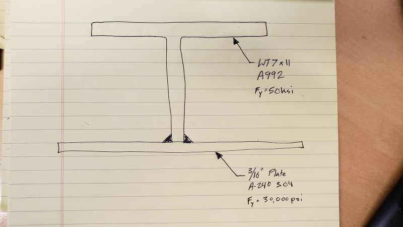
Any help or guidance on the following is greatly appreciated! I'm tasked with analyzing a built-up I-shaped member composed of A-992 WT7x11 and 304 SS 3/16" plate, under simply supported combined major axis bending and axial compression. I've done some research and believe using the transformed section (A.K.A. transformed width) method to find the moments/stresses followed by AISC 360-16 F4. OTHER I-SHAPED MEMBERS WITH COMPACT OR NONCOMPACT WEBS BENT ABOUT THEIR MAJOR AXIS to find the allowable moment is the way to go. However, what I'm getting hung up on is the requirement that the entire section must remain within the proportional limit (i.e., no part of the section can plastically yield) when using the transformed section method and from what I understand, AISC 360-16 F4 is based on some plastic yielding happening throughout the section. Is there a way to modify AISC 360-16 F4 to limit the yielding to the elastic limit or maybe there's another method that I should be using? Thanks in advance for your help!

20210723_121618_jsysyx.jpg
 
Replies continue below

Recommended for you

A similar question was discussed in Modern Steel where they were reinforcing a 50ksi I-section with 36ksi plate. It discusses how to apply each limit state included in F4.

When you calculate your section properties, "My" will use Fy of 30ksi since that is when yielding will first begin. For "Mp", you use Fy of 30ksi and 50ksi (this should be coordinated with your "transformed width").

Structural Engineering Software: Structural Engineering Videos:
 
Perfect, thank you. Any way you know the date of that publication?
 
Thanks, and I just realized you already provided the link. Just like having the right tool for the job, there's nothing better than finding the correct method to analyze your problem.

Maybe you can help with another issue I'm having. I need to analyze a similar built-up member, basically the same as before but replacing the WT with a structural A-36 angle. Doesn't seem like this fits anywhere in AISC 360 other than F12. UNSYMMETRICAL SHAPES. Any ideas for a straight forward analysis?
 
How are you reinforcing the angle? If you're just thickening an angle leg then you may be able to use F10 if the plate isn't too much wider. If you're attaching the plate to one of the toes, then you're in F12, but I'm not sure what value you would use for Fcr. Maybe ignore some of the plate and design it like a channel...?

Structural Engineering Software: Structural Engineering Videos:
 
What I'm actually doing is using the WT or angle to stiffen a plate. So I'm using a width of 16 x plate thickness for the tension flange, see below. I like your idea of conservatively using only part of the plate in order to analyze it as a channel, but I don't see a part in AISC 360 applicable to analyzing channels other than F2. DOUBLY SYMMETRIC COMPACT I-SHAPED MEMBERS AND CHANNELS BENT ABOUT THEIR MAJOR AXIS but I believe that is for singly symmetric channels whereas this would be asymmetric.
20210723_144509_mleoqd.jpg
 
If I remember right, the coefficient of thermal expansion is different for carbon steel and stainless, so you may have some thermal stresses and deflections that you wouldn't normally expect.
 
The CTEs are different by about a factor of two. You had better check that also.

= = = = = = = = = = = = = = = = = = = =
P.E. Metallurgy, consulting work welcomed
 
What's the full picture of this structure? The plate that you're stiffening might provide restraint, in which case the code buckling capacity calculations would be conservative if you apply them to your design section as though it exists in isolation.

Under what conditions must the steel not yield? The code safety factors might be enough to prevent yielding under working loads even though they're based on plastic capacity in some cases.

Both comments can be safely disregarded if you don't need the leanest design.
 
Great questions... The angle or WT is one of many external rafters that support a conical plate roof on an API650 tank. Very interested to hear your thoughts on if the plate will provide restraint and if AISC F4 equations will be conservative. Note that the SS plate will be in tension.

The roof design parameters are typically a live load, snow load, minimal external pressure at a design temperature around 200F.

I agree, I'll need to incorporate thermal expansion into the analysis.
 
The plate will act as a continuous twist restraint to the composite beam even though it's at the tension flange. Presumably the stiffeners are at reasonable spacing compared to the plate stiffness so the increase in flexural buckling capacity would be substantial.
 
I agree the cone roof plate will act as a twist restraint but not sure how to quantify it in relation to flexural buckling. Any idea on that? Know of a resource to use?
 
Am I the only one who's concerned about galvanic corrosion issues when these two different metals are welded together?
 
Or are you implying that Lb = 0ft and F4.2 Lateral-Torsional Buckling will not apply?

"When Lb ≤ Lp, the limit state of lateral-torsional buckling does not apply."

"Lb = length between points that are either braced against lateral displacement of the compression flange or braced against twist of the cross section, in. (mm)"
 
JP said:
Am I the only one who's concerned about galvanic corrosion issues when these two different metals are welded together?
That's where my head was going too. But since no one else seems to be concerned, maybe it's not an issue?
 
I was also concerned, but if it's in a dry environment (no electrolytic solution), then it won't happen. Hopefully they have sufficient environmental controls in place to prevent it.

I know there are methods for joining carbon and stainless steel, but I'm interested in the process. I've never specified it before and don't know any details.
 
Status
Not open for further replies.

Part and Inventory Search

Sponsor