Continue to Site

Eng-Tips is the largest engineering community on the Internet

Intelligent Work Forums for Engineering Professionals

  • Congratulations KootK on being selected by the Eng-Tips community for having the most helpful posts in the forums last week. Way to Go!

Bridge Overhang Design Rebar Development 2

Status
Not open for further replies.

beng_78

Structural
Feb 24, 2020
3
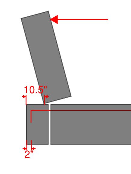
I'm designing a deck overhang for barrier impact load in Washington State. The state standard details have the barrier face 10.5" from the edge of deck.

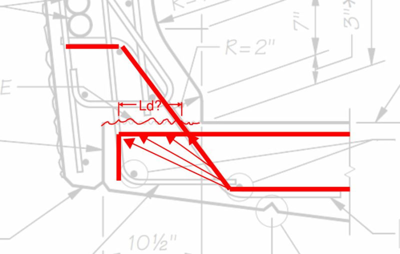
The checker has indicated that the rebar we're using (#5 @ 6") has insufficient development length for the critical section at the barrier face, when considering the length from the end of the cantilever (10.5"-2" = 8.5"), so we need to reduce our capacity by the ratio of ld prov/ld req.

In looking through multiple DOT calculations for this, I have found two states that consider the development of the bar from the cantilever end and show it in their examples. Most do not show a calculation for it (including WSDOT). Some states provide a 180 degree hook, including WSDOT, but others do not (CA, MO).

It seems like different states have different approaches to this, and I keep going back and forth on how to interpret development in this scenario. I'd especially like to hear from people in states where a hook isn't detailed.
 
Replies continue below

Recommended for you

Is my depiction of your situation below accurate? If so, at least on a theoretical basis, I agree with your checker. You could add the width of your barrier compression block length to the development value but that's not likely to change anything appreciably.

c01_d05rol.jpg
 
I don't know WSDOT's details, but I'm fairly sure the "face" beng_78 was referring to was the inside face, usually referred to as the front face. So, the barrier is 10.5" thick, with the rear face at the edge of the slab. The critical section for failure is through the deck at the front face of the barrier.

In any case, I would tend to agree with the checker also. You need to either reduce the capacity or provide a hook.


Rod Smith, P.E., The artist formerly known as HotRod10
 
BridgeSmith said:
So, the barrier is 10.5" thick, with the rear face at the edge of the slab.

I was afraid of that. If that's the case then I change my theoretical answer to be that this probably doesn't work at any bar size as it's rather like a toe-less retaining wall. I'd love to see some testing results to prove me wrong though. And I wouldn't put it past the DOT's to have those. This would definitely make my practical answer: give the DOT what they want and count your blessings that they're not looking at it even more critically.

Is it accurate to assume that we'd be dealing with a non-roughened shear friction plane for something like this? Shear key?
 
Neat. I'm curious, in considering this joint, would you bridge guys consider it:

1) Shear friction with the diagonal bar providing the clamping force OR?

2) The diagonal bar effectively acting like a tension tie dragging the shear back into the deck like a diagonal stirrup in a beam?


c01_xij89z.jpg
 
I'm not sure how the failure mode looks for concrete barriers, but I suspect it's similar to what we see with the steel posts in our railing - a 'punching shear' failure of a section of the deck, where a chunk of the deck breaks out mostly horizontal.

For our TL-4 railing, we provide stirrups that anchor the concrete at the posts back into the interior of the deck.

Concrete barriers are generally considered to distribute the force from a vehicle impact over several feet (up to 12' or more, depending on the configuration). So, the force per foot is not huge.


Rod Smith, P.E., The artist formerly known as HotRod10
 
We don't get too much into the theoretical mechanisms and internal stresses. We mostly just build a configuration we think will work at the testing facility in Texas, and run a truck into it to see how it fares.

Rod Smith, P.E., The artist formerly known as HotRod10
 
The railings fare far better than the numbers say they should, so it's worthwhile to actually test the configurations.

There's a similar phenomenon with concrete bridge decks on steel girders. For decades, we've been designing them as multi-span beams and reinforcing them based on a flexural failure mode. Recent full scale testing showed that decks don't fail in flexure; they fail in punching shear, at about 5 times the loading they were expected to. The AASHTO spec now includes provisions for "empirical" deck design, with prescribed reinforcement that's less than half of what we've traditionally used.

Rod Smith, P.E., The artist formerly known as HotRod10
 
So, bottom line, y'all think I need to provide ld from the point of load application to the edge of deck for a 180 degree hook (in my case), or reduce my capacity based on ldprov/ldreq.

Never checked this in CA. Their details have straight bars to the edge of deck, so ld would probably be longer than the barrier width, especially for larger bars. Although, CA deck design memos kind of gloss over overhang design by saying if your overhang is less than 1/2 your slab interior span, your deck design is fine. To satisfy this ld requirement, I need an additional #5 @ 12. WSDOT's overhang design example just calculates required As at the critical location but doesn't look at development.
 
Having the barrier on the deck, instead of hanging off the edge, makes a big difference. In the WSDOT detail I linked to, for instance, if all 18.75" of the barrier was on the deck, the length available for development of the deck reinforcing beyond the critical section almost doubles.

Rod Smith, P.E., The artist formerly known as HotRod10
 
The F barrier has a bottom of about 4", so you don't quite get double. An additional 4" would be almost sufficient for a 180 degree hook for a #5 bar (my situation), but not for a straight bar (Caltrans Details).

Just interesting that it doesn't seem to be considered in some DOTs but is in others. I would love to know rationale.
 
You're right beng_78, assuming they kept the slope on the rear face. I was comparing to a more typical barrier where the rear face is vertical.

The WSDOT barrier seems like it would very difficult to form up, and I'm not sure what the advantage is to having it hang over the edge of the slab. Overall, it doesn't save much concrete, and as you've discovered, it makes it much harder to adequately develop the slab reinforcing. The slope on the backside seems like alot of extra work to save a couple inches on the width of the deck. I'm sure they have their reasons for doing it that way, but I'll be darned if I can see it.

Rod Smith, P.E., The artist formerly known as HotRod10
 
Yes. We always hook the deck bars at the end with a 90 degree hook. I have never left them straight or done a 180. If the deck isn't thick enough for a full #5 tail and the required cover (our decks are typically 8.5" but we sometimes thicken the overhang), you can bend the tail up into the barrier or sideways. Either that, or you can show the tail down on your drawings and plead ignorance when someone calls you out on it!

I have also never designed a barrier that is only 10.5" thick. Normally, the single slope barriers we design are more on the order of 14" to 18" thick at the base. The crash tested barriers we steal from TX DOT are more on the order of 12", however those don't typically sit right at the edge of the deck since there are some fancy thickened pilasters every so often that do extend to the backside of the deck.

Either way, with a barrier that thin, you're probably looking at having to hook the bar and rely on l(prov)/l(req).
 
Status
Not open for further replies.

Part and Inventory Search

Sponsor