Continue to Site

Eng-Tips is the largest engineering community on the Internet

Intelligent Work Forums for Engineering Professionals

  • Congratulations waross on being selected by the Eng-Tips community for having the most helpful posts in the forums last week. Way to Go!

Bracing of Welded I-Girder 1

Status
Not open for further replies.

hdn32

Structural
Sep 28, 2004
51
Dear forum member,

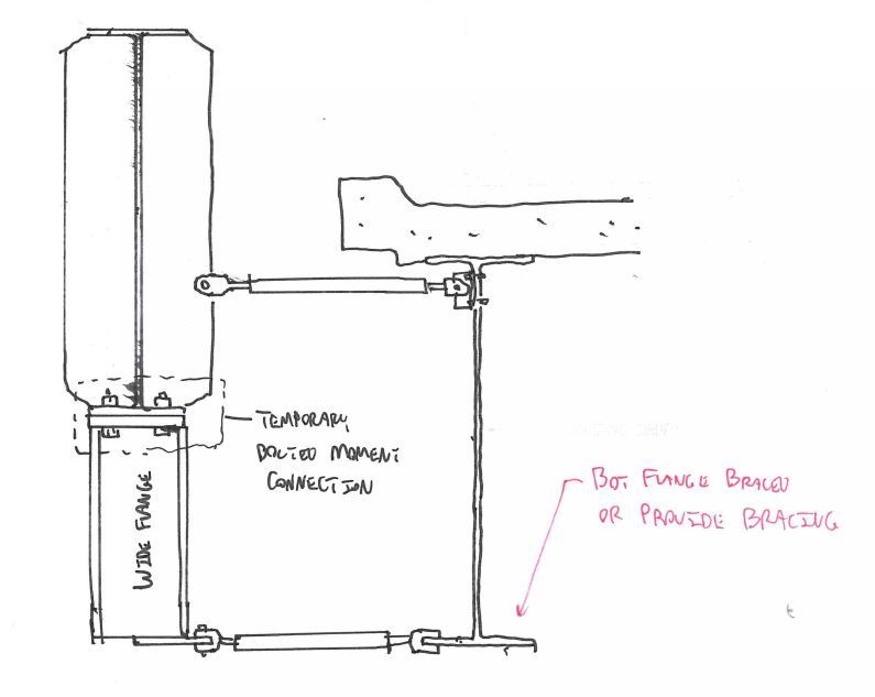
Currently I am putting together details of temporary bracing that will be used during the erection of the first new I-girder of a new bridge.

We have quite a few debates/discussions within our office about lateral torsional buckling mechanism, bracing types/configurations, and practical design & detail for temporary/permanent bracing systems. But we did not come to an agreement on this topic.

Therefore, I would like to put sketches of bracing schemes on this forum with hope to get additional opinions.
Please take a look at the attached PDF files and let me know your comments about whether or not the details make sense to you.

Following are my references:
“Is Your Structures Suitably Braced?” by professor Yura
“Guide to Stability Design Criteria for Metal Structures” by Ronald D. Ziemian
“Bracing System Design - Volume 13” by FHWA
Several threads in on Lateral Bracing of I-girder/Beam

Thank you in advance,

hdn32
 
Replies continue below

Recommended for you

I like detail 1 - consider that during construction the new beam will be loaded and deflect down relative to the existing structure. Detail 1, with braces in the horizontal orientation, will allow this deflection with the least amount of lateral deflection. If you can make these braces longer, it should reduce the final lateral deflection from the braces even more.

If the beam's compression flange is laterally restrained, then it is braced.

 
hdn32 - Checking some of your listed references, appears they concern creating a stable structure by bracing new members strictly between themselves - somewhat tricky. For your sketch, you have a big advantage - what looks to be an existing, adjacent, freestanding bridge which I assume is fixed in place and stable. If true, this should allow simplification of the temporary bracing. Can you show us a sketch of the new girder, showing the length, girder supports, and the location of gusset plates where bracing can be connected?

[idea]
[r2d2]
 
I like Teguci's concept of keeping the braces horizontal so as to minimize transmission of vertical forces. However, I feel that all of your details are working that little nub of curb concrete pretty hard, particularly the details that rely on the moment capacity of the nub.

I propose the torsional bracing detail below. I believe that it would have the following features:

1) Horizontal braces again.
2) Doesn't damage the concrete.
3) Convincing LTB restraint for both positive and negative bending regions (not sure if this is a simple span or continuous girder.
4) Ought to be about as economical as your details.

I'm assuming that the bottom flange of the existing girder either is, or could be, braced laterally.

Capture4_uukdcr.jpg


I like to debate structural engineering theory -- a lot. If I challenge you on something, know that I'm doing so because I respect your opinion enough to either change it or adopt it.
 
SlideRuleEra,

Please find the attached PDF file of the plan showing the additional info.
Yes, the the existing bridge is in good conditions and can be of our advantage.

Thank you for your comments and please let me know if you have additional question/request.

hdn32
 
 http://files.engineering.com/getfile.aspx?folder=30f47d57-c1ab-404c-be93-47ec2d35004a&file=PartialPlan-Forum.pdf
Hi Kootk,

Thank you for your comments and preference.

However, we are not allowed to drill and/or weld into the new I-girder.
For my curiosity, could you please let me know why you want to add the stub (wide flange) and have the new strut go perpendicular to the existing girder instead of connecting new strut to the lowest bolt hole on the gusset plate of new girder?

Regards,

hdn32
 
I agree with Koot's method for bracing. It's far more efficient than relying on the concrete nub to transfer the forces. I believe he's keeping the bracing horizontal to prevent transmission of the vertical forces as Teguci mentioned.
 
You could also moment connect the stub to the girder stiffeners directly. That would be easier really. Just use a longer stub and run it up the left side of the new girder. Remove them one at a time as you add in permanent bracing.

I used horizontal bracing between girders, arranged as shown, for three reasons:

1) limited transmission of vertical displacement between girders

2) healthy torsion lever arm on existing side.

3) healthy torsion lever arm on new side.

I like to debate structural engineering theory -- a lot. If I challenge you on something, know that I'm doing so because I respect your opinion enough to either change it or adopt it.
 
hdn32 - Quite a project, I understand the reason for debates in your office. The reinforced concrete bridge deck overhang should be more than adequate as a connection point for temporary braces. The problem is how to make that connection.

Details 2, 3 and 4 rely on concrete anchors. The safe load rating of any reasonable size concrete anchor is going to be a (very) weak link in the temporary bracing. Also, if possible, temporary connections to the underside of bridge deck should be avoided - constructability issues. IMHO, all three of those details should be rejected.

For Detail 1, the comments above apply for use of a concrete anchor. Use of a thru bolt has possibilities. Drilling through an existing bridge deck is a challenge - a lot of heavy longitudinal rebar to miss - but it can be done. I'm not wild about having to work with the bolt under the overhang, but believe it is the best way. In Detail 1, suggest omitting the lower pipe brace assembly, just use one - the upper one. If you would be more comfortable using both pipe braces, it won't hurt - but I don't consider it necessary. Make use of the detail at each and every available gusset plate.

When the second girder line is set, the permanent diaphragms can be installed between girder line 1 and girder line 2. This should take care of LTB issues when the new deck is placed.


[idea]
[r2d2]
 
SlideRuleEra,

Again, thank you for getting back to me with your thought/comments.

Yes, we are leaning toward using detail 1 as you suggested.

As far as frequency of bracing, the I-Girder is okay with maximum 50ft & 30ft unbraced length for straight girder and curved pieces respectively. However, I will calculate the required strength & stiffness of the temporary braces, then I'd look at the capacity of the anchor/thru bolt connections and availability of gusset plate to make my decision. I will definitely be on the conservative side.

Regards,

hdn32
 
hdn32 - A lot of unknowns and variables in temporary construction. Also a lot of potential risk to workers and possibly the public. When you can get redundancy as easy as the drawings indicate... IMHO, forget the calculations (other than to make sure there are enough braced points) - use them all.

Read about this one, with three fatalities, very similar to your project. It was national news 12 years ago: Link

[idea]
[r2d2]
 
Hdn32:
There have been some good and important points made in the posts above. Are you going to erect the two lines of girders kind of in unison (side by side) from pier to pier or are you going to erect girder line #1 full length, then girder line #2 next? Tagging on to SRE’s last post, I like your scheme #1 best also. I would offer the following suggestion. Given the existing bridge curb detail, you could fabricate steel shoes which would fit over the top of the curb and down its inside slope and then have a second part bolted to the top curb shoe. This outer (2nd) part would have a horiz. leg that fit up under the curb, locking the shoe to the curb, maybe some shimming needed, and it could have a vert. limb which allowed bolting (pinning) of your adjustable length braces, at a more favorable distance apart, but still pretty much in a horiz. orientation. Then a few concrete anchors would be used just to fix the shoes to the curb. The anchors would not be taking all of the primary bracing loads. If the side by side erection scheme is used, you could just jump 6 or 8 of these curb shoes on down the line as permanent bracing frames are installed btwn. the girders and erection progressed.
 
Is there any chance that the gusset plates on the new girder line up with the gussets on the existing bridge?

 
@ SlideRuleEra: Thank you for the link & headup.

@ Dhengr: There are actually 5 girder lines and we are doing "side by side" erection. The 2nd line will be picked with permanent X-bracing/Diaphragms installed on both sides. Thank you for your opinion and suggestion of the bracket/shoe detail.

@ BridgeEI: There may be a couple locations along the entire girder line only. Thank you for your question. Should you have additional comments and/or questions, please let me know.
 

Please be cautious with any lateral bracing arrangement - you have to be sure that the steel structure can deflect as anticipated when the deck is placed. KootK had suggested a moment connection between the stub and the (existing?) girder stiffeners. That may not be wise unless I'm coming into this thread a bit late and am missing something. Perhaps all of the temporary connections to the existing bridge are to be removed before the deck is placed, making my comment moot.


Ralph
Structures Consulting
Northeast USA
 
RHTPE said:
KootK had suggested a moment connection between the stub and the (existing?) girder stiffeners

You'll have to be more specific RHTPE. I recommended a detail specifically designed to allow differential girder deflection. It involved a stub wide flange moment connected to the new girder as shown in my sketch above.

I like to debate structural engineering theory -- a lot. If I challenge you on something, know that I'm doing so because I respect your opinion enough to either change it or adopt it.
 
@ Bridgebuster: No, I wish we could do pair pick with permanent braces installed between girders. Thank you.

@ Ralph (RHTPE): We are concerning about the stability of the 1st piece after crane releases. Yes, all temporary braces (to existing bridge) will be removed prior to the pouring of deck. Thank you.
 
Status
Not open for further replies.

Part and Inventory Search

Sponsor