Continue to Site

Eng-Tips is the largest engineering community on the Internet

Intelligent Work Forums for Engineering Professionals

  • Congratulations cowski on being selected by the Eng-Tips community for having the most helpful posts in the forums last week. Way to Go!

Box Beam Connection Detail 1

Status
Not open for further replies.

WARose

Structural
Mar 17, 2011
5,594
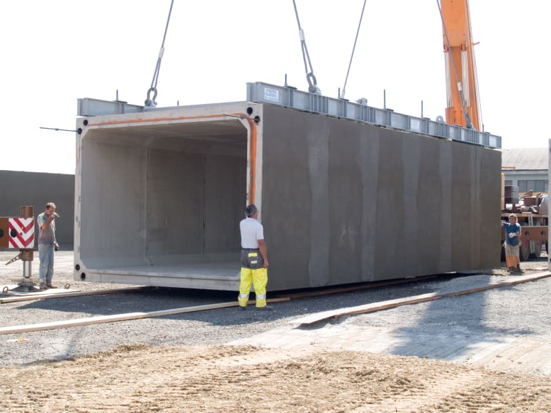
I am using a number of precast box beams (they will NOT be prestressed, they will be cast on site and lifted into place) as a utility tunnel. (I.e. it will be filled with pipe and conduit.) There will also be some heavy point loads on the roof of this thing.

Does anyone know how the joint detail should look? (Please see the attached pic.) I'm figuring we'll cast it in about 20' segments. But the joint detail worries me because these are some AASHTO level type loads on the roof.

Thanks.
 
 https://files.engineering.com/getfile.aspx?folder=5acf675e-d7a7-458a-b82c-3c12e1ffd9e1&file=tunnel.pdf
Replies continue below

Recommended for you

There is probably a more elegant/efficient way of doing this - but could you leave a 2'+/- pour strip in between adjacent panels? That way you could cast in a shear key, leave some rebar sticking out, and really tie the two panels together with cast in place concrete. I believe a similar detail is used on precast bridge decks.
 
I saw one detail some years back for something similar in a bridge. It kind of looked like they were making the connections via HSS to HSS (I assume attached by embedded bolts and field welded with a flare weld). But that's just eyeballing it in the field.

Hotrod10 is a bridge guy so I hope he sees this.
 
WARose:
Offset the joints of the top slab and the “U” shaped box, so they don’t both happen at the same vert. plane. Do you need any sort of a water tight joint btwn. the various parts, a water stop of some sort or a O-ring type gasket, etc? Do you need any shear connectivity btwn. the various parts, so they can transfer some load and not move/settle/shift independently? Do you want some shear keys in the side walls and bottom of the “U” shaped box, maybe a ship-lap type slip joint, or 2x4 sized shear key on three sides and the top? Can you actually lift and position and bed 20’ long sections or would 10-12’ long be easier to handle? While not technically post or prestressed, make the four corners larger blocks of conc., maybe larger fillets, so you could put a couple of tensioning ducts in each corner. Then, every 10’, you would tension the new unit back to the previous unit, much like they do on bridges built up of short box sections.
 
I would expect to see a lap joint similar to what is done for precast culvert sections or a grouted joint with weld ties like what is employed for decked bulb tees. A couple of examples of grouted joints are below:

WSDOT standard Details

GUIDELINES FOR DESIGN AND CONSTRUCTION OF DECKED PRECAST, PRESTRESSED CONCRETE GIRDER BRIDGES See pages 51 and following (pg 61+ of the pdf)

You can look at those, but my best advice is to contact a precaster in the area and ask them what type of joints they could provide for your application.

I take that back - my best advice is call out an 5x8 precast box culvert with zero fill, to be designed by the precaster for HL-93 loading. Make sure it's clearly communicated that the 8ft is the height.
 
I really appreciate this HotRod. (Wish I could give you more than one star.) I've seen that shear key detail before.....but just eyeballing it, it doesn't seem like much shear could pass. (Unless they are saying the (2) longitudinal bars will engage the bars in the other direction. never done it quite like that. Need to study this more.)

Thanks again.
 
Sorry for the quick hit and run response; it was lunchtime.

Anyway, the question I have is have you talked to a precast supplier who suggested this or said they could fabricate the sections as you've shown them? I haven't seen anything like it available from the precasters around here. Precast items that aren't fairly standard (i.e. the forms for them are readily available) are usually very expensive - cast-in-place would be much cheaper than a non-standard section.

Let me pitch again a standard precast box culvert section. If you can do something to fill in the gaps on each side, that will be the easiest and least expensive option. With 18" available, you could also do the precast 5x8 box and throw a 10" CIP reinforced slab over it. For a 5' span, the precast top slab would be 8". It would just have heavier welded wire mesh than typical, for a very nominal cost increase. The box culvert sections do have 12" x 12" triangular haunches in the corners, so if you need a certain width of flat slab inside, you might need to bump up the size.
 
Anyway, the question I have is have you talked to a precast supplier who suggested this or said they could fabricate the sections as you've shown them?

It's going to be fab'd on site. No outside contractor (like Metromont or whomever). That directive has come from above.

Precast items that aren't fairly standard (i.e. the forms for them are readily available) are usually very expensive - cast-in-place would be much cheaper than a non-standard section.

Your links have given me some ideas. I'm now looking at embedded, inserts to make the connection. May post once I have it worked out.

Let me pitch again a standard precast box culvert section. If you can do something to fill in the gaps on each side, that will be the easiest and least expensive option. With 18" available, you could also do the precast 5x8 box and throw a 10" CIP reinforced slab over it. For a 5' span, the precast top slab would be 8". It would just have heavier welded wire mesh than typical, for a very nominal cost increase. The box culvert sections do have 12" x 12" triangular haunches in the corners, so if you need a certain width of flat slab inside, you might need to bump up the size.

I thought of a culvert as well.....but if you see those 2' flanges (or cantilever, or whatever) in my pic, that's going to be picked up by a beam. (This thing isn't sitting on the ground.) A typical culvert is lacking that.
 
Oops, I missed the part where this is suspended (?) Let me think about that for a minute...
 
So this is essentially hanging between 2 bridge girders?

Precast RC beams actually. This isn't a bridge project....but it's got some mighty heavy loads.
 
Yeah, in that case steel angles anchored with embedded studs with a narrow steel plate welded along the edges to tie the angles may be your best bet. It would be similar to the weld ties (see Section C, Alternate 2 on this detail, but since it's only 10', I'd recommend just running it all the way across. Grout the groove and you're done.

Edit: If the welds are continuous and solid, it should produce a watertight joint, too.
 
thanks again HotRod. May post when I get it sketched up. (If I can get the numbers to work.)
 
another possibility : beams cast on site + post-tensioning (similar to these boxes)
Sert-System_post-tensionato_2_ikdtqw.jpg
 
Status
Not open for further replies.

Part and Inventory Search

Sponsor