Continue to Site

Eng-Tips is the largest engineering community on the Internet

Intelligent Work Forums for Engineering Professionals

  • Congratulations cowski on being selected by the Eng-Tips community for having the most helpful posts in the forums last week. Way to Go!

Big capacitors Oh Boy! 1

Status
Not open for further replies.

itsmoked

Electrical
Feb 18, 2005
19,114
Look at what just landed on my desk.

20190201_194109_tq6ove.jpg


20190201_194128_xzj4vc.jpg


I want to take care of my Precious.

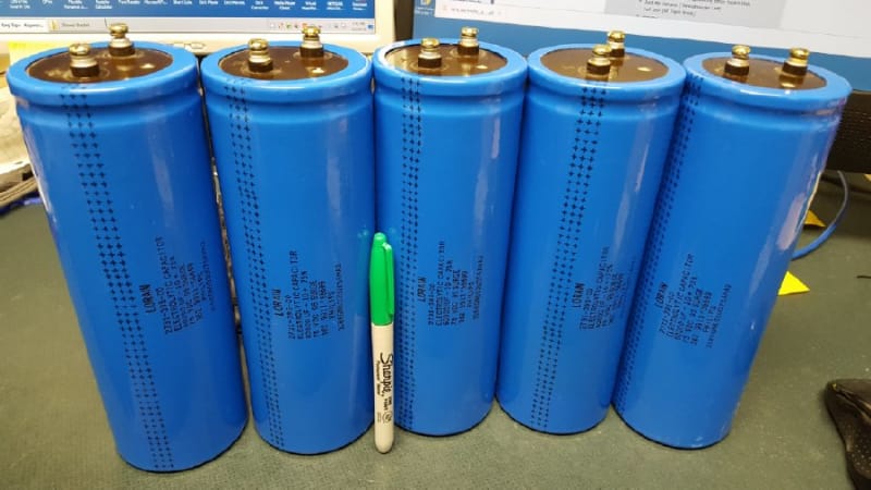
New. Used for a week 18 years ago. Never powered on since. Kept in temp stable 68F since then.

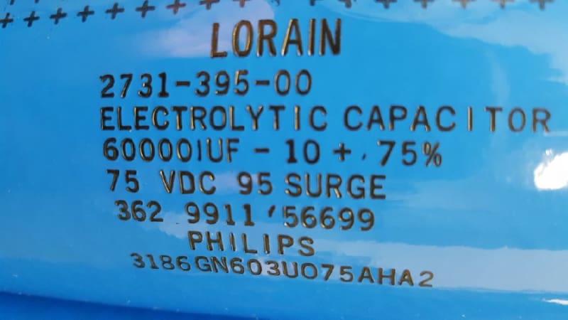
What should I limit the leakage current to as I reform these babies?
I suppose I'll take a whole day to ramp them.

I feel a 18650 spot welder coming on..

Keith Cress
kcress -
 
Replies continue below

Recommended for you

My high school physics teacher had a 1 F capacitor he used for demonstrations; he'd form and charge for a day or two and then dropped a buss bar across the terminals. Very spectacular and satisfying.

TTFN (ta ta for now)
I can do absolutely anything. I'm an expert! faq731-376 forum1529 Entire Forum list
 
In my 7th grade science fair I got a bank of considerably smaller capacitors and charged them to about 400V then discharged them thru a sliver of shaved aluminum foil. Even after warning them, at the inception of the plasma ball, I think some of the judges wet themselves.

Keith Cress
kcress -
 
"at the inception of the plasma ball, I think some of the judges wet themselves." [shadeshappy]

I built a thermocouple spotwelder with about 1/100 that amount of Farads, and it completely fried 24 gauge type K wires at full charge. Had to put a voltmeter on the leads, and a 2-stage charger circuit (one of the momentary buttons had a current limit resistor in series) to tone it down a bit.
 
We had this little bank built to replace a woefully under-sized DC link reservoir installed in our UPS which periodically used to brew up. The OEM didn't want to know so we took matters into our own hands: our in-house solution was 15x 4700uF/400V in parallel - the ripple current handling was 'sufficient'. :)

Cap_Bank_didc9q.jpg
 
>7th grade science fair
Keith, did you take first place at that fair?
 
I think it was about grade 11 when I built a Jacobs Ladder (traveling arc) for a science fair. I used a 15,000 Volt neon transformer, installed in a fume hood with the window screwed down.
It was featured in the blurb the school put in the local weekly inviting the community to the science fair.

Bill
--------------------
"Why not the best?"
Jimmy Carter
 
danw2 said:
Keith, did you take first place at that fair?

Naw. Only second place out of 400 entries.

For eighth grade I built a six foot high Tesla coil. It had a primary spark gap that was two 2" square plates whose gap between one end was adjustable. They had to be that size so they could get some cooling.

[tt][pre]Like this:
o o
\ /
\ /

^
|
gap
[/pre][/tt]
When the primary coil and bank of caps resonated at 25kV the entire two inch gap was sky-blue fiercely angry arc. You could couldn't even shout over it and be heard. Honestly I dug that more than the 14" sparks off the secondary. [lol]

They didn't really listen to my warning that year either and since the judges turn over every year they didn't remember me and were emotionally unprepared for the situation. They all leaped back and one even dropped his clipboard.
2qu5d3o.gif


I built the thing entirely myself with no help from anyone but they could not believe I hand wound the six foot 1-1/2" diameter secondary with 24AWG magnet wire. It was quite magnificent with it's metallic kind-of-golden glow from the wire varnish. I was methodical about it and wound it over about a week while watching the boob tube. I learned early on to follow what I was doing with masking tape after fumbling it once early on. (instant rats nest) I could pause the process with masking tape any time I was done with a session.

I believe some skepticism about that landed me in a second place again. :/

Keith Cress
kcress -
 
Since they're "only" 60mF (in the era of Farad supercaps), even a smallish current would charge them rapidly.

So perhaps a voltage (current limited) manually stepping up over hours would be best. As opposed to "current".
 
I put one on a lab supply. I hooked a voltmeter across the cap and ran the supply current thru a 6-decimal place HP bench ammeter.

With the current limit all the way down I set the disconnected supply to 20V. I then turned up the current limit to 10mA. It took about 3 minutes for the cap to reach that. Once it did I left it for 5 minutes and came back to see about 1.5mA still going in. I bumped up the 20V to about 22V and after about 3sec brought it back down to 20V. The current went briefly backwards draining into the bench supply then went forwards again and ran back up to about 1mA. Clearly there was about 1mA of leakage at 20V. After an hour I disconnected the supply, turned it up to 40V, reconnected and watched, all with big safety glasses on. That took about 4 minutes to raise the voltage. E = ∝V2? After an hour it was leaking about 800uA.

I get the feeling if these had all been hit with 75V pushed by 480V 100A service it might have turned out not too well.

I expect the leakage to diminish but haven't had the time to form it long enough.

Keith Cress
kcress -
 
Hey look, their baby brothers turned up in a EEVBlog tear-down.

No one believes the theory except the one who developed it. Everyone believes the experiment except the one who ran it.
STF
 
Status
Not open for further replies.

Part and Inventory Search

Sponsor