Tek-Tips is the largest IT community on the Internet today!

Members share and learn making Tek-Tips Forums the best source of peer-reviewed technical information on the Internet!

  • Congratulations LittleInch on being selected by the Eng-Tips community for having the most helpful posts in the forums last week. Way to Go!

Bending stress in a ring

Status
Not open for further replies.

Denboone

Mechanical
Joined
Mar 13, 2017
Messages
7
Location
GB
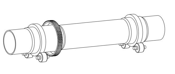
I can't find any formulas for my problem. I work on a purification dryer who's fit in 2 large rings. Each ring roles on 2 rollers each make a angle of 28° with the vertical axes. The rings have an internal diameter of 2568mm and an outside diameter of 2848mm. It has an rectangular section 260mm wide and a height of 140mm. There is product in one ring with a force of 125kN 136mm next to the center of the ring and a force of 480kN in the center of the ring. These 2 are vertical forces. The ring is supported with 2 reaction forces in the rollers under need it. These have the angle of 28° with the vertical axes. Anyone who can help me? Thanks.
 
Droger_vluv6g.jpg


This is a picture of the dryer. The problem with Roark's formulas for rings is that the force C is not there. The force is the weight of the dryer and this does not just push in the middle the ring downstairs but the force is also present everywhere in the ring not just on the upper point.
 
You need to superpose two loading conditions: one with two radial loads at an angle and a bottom support, the other one with a circumferentially distributed load and a bottom support. By suitably choosing loads and orientations, the bottom load is made to vanish.

prex
[URL unfurl="true"]http://www.xcalcs.com[/url] : Online engineering calculations
[URL unfurl="true"]https://www.megamag.it[/url] : Magnetic brakes and launchers for fun rides
[URL unfurl="true"]https://www.levitans.com[/url] : Air bearing pads
 
Ah OK thanks, I'm gonna try this with roark's formulas, if I have problems calculating this stress with this (and probably it will :p) I'll ask you again. Thank you in advance.
 
@robyeng what is the meaning of the M and N in the tables. Do I have to multiply these with other values?
 
M = bending moment (see the legend here attached for the units). See also the note for + or -

N = axial force (see the legend here attached for the units). See also the note for + or -

"m" and/or "n" are the coeff listed according to the different angles (there is a mistake in the list : they are listed as M and N, but they should be deemed as m and n)
 
 http://files.engineering.com/getfile.aspx?folder=9db67fda-7b2b-47a1-b83c-434b965de87e&file=Kittel_coeff_legend.pdf
Are you sure everything is correct in the legend cause the bending moment M is in kNm/m. Shouldn't be kNm?
 
yes, it is correct. the calculation are always done per unit of length (in this case 1 meter of pipe). If the pipe is 2.5 m (for exemple), you have to multiply the result x 2.5
 
I think it's impossible to combine 2 loads. If i calculate W in table 9.2 point 5 (roarks formulas) with the 480kN circumferentially distributed load and further on the bending stress with the obtained result bending moment I become results 3 to 4 times higher than my FEA analyse with autodesk inventor.
 
@roby That's weird because the ring I have to calculate has a width (length) of 0,26m the obtained bending moments are around 10kNm which is very small.
 
Status
Not open for further replies.

Part and Inventory Search

Sponsor

Back
Top