Continue to Site

Eng-Tips is the largest engineering community on the Internet

Intelligent Work Forums for Engineering Professionals

  • Congratulations waross on being selected by the Eng-Tips community for having the most helpful posts in the forums last week. Way to Go!

Bending of flange leg

Status
Not open for further replies.

merba661

Structural
Aug 18, 2016
1
Capture_fmb0vb.png

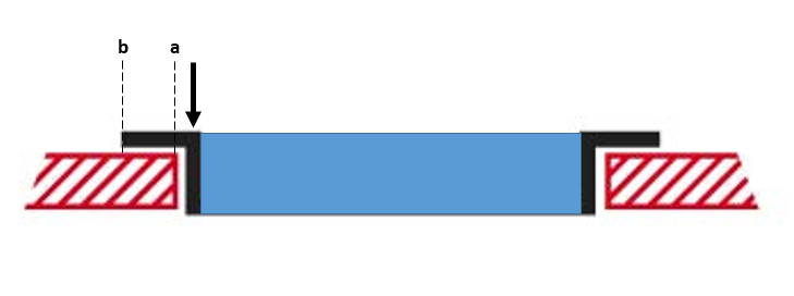
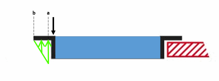
I have a situation basically like this picture. It is essentially a vent installed into an opening with a flange around the perimeter that bears on the surrounding of the opening - nothing else holding it in placce. A pressure on the face results in a distributed load on the perimeter which I represented on the picture with the black arrow. It is pretty much constrained from moving horizontally except for a small gap around the perimter between the frame and the opening. So my question is, when it comes to checking the bending of that flange, what would one use as the dimension of the moment arm? The distance from the black arrow to 'a' or the black arrow to 'b'?
 
Replies continue below

Recommended for you

I'd be using b. But that would be conservative. It reality it's probably somewhere between a and b.
 
I would assume the reaction is at the center of the bearing width, to the left of "a", which is dependent on the allowable bearing stress in the material to the left of "a." If the material is steel, then the reaction is essentially at "a." If the material is concrete or wood, then the reaction will be to the left of "a."

DaveAtkins
 
SRE's approach is the way I'd go. mind you this is very conservative. There is data out there for flange bending (McCombs, Supplement to Bruhn) which is less conservative, but still very conservative (so hand calc super conservative, data very conservative, test is right on). if you can (and if you have to to show it good) test a sample of the flange and know what it's good for.

another day in paradise, or is paradise one day closer ?
 
Merba661:
In determining where the reaction point will be or the reaction distribution, think in terms of how the angle shape, or structure, will deflect, rotate or deform under load. The greatest deflection wants to occur at ‘a’, thus the bearing load or stress will be greatest at that point and diminish as you move out on the flange to point ‘b’. SRE’s sketch is a darn good approx. for conc. or wood, where some crushing will likely occur in the reaction material until bearing equilibrium is reached, thus highest bearing stress at ‘a’ and diminishing as you move out to ‘b’, where it may not be zero. For a steel bearing material I would tend toward DaveAtkins’ mid point btwn. ‘a & b’ because it is likely that the steel flg. the angle is bearing on will also deflect to some extent under load, thus moving the center of bearing toward ‘b’.
 
Status
Not open for further replies.

Part and Inventory Search

Sponsor