Continue to Site

Eng-Tips is the largest engineering community on the Internet

Intelligent Work Forums for Engineering Professionals

  • Congratulations cowski on being selected by the Eng-Tips community for having the most helpful posts in the forums last week. Way to Go!

Bending moment in triangular frame

Status
Not open for further replies.

jackyhong

Mechanical
Mar 8, 2018
2
Hello everyone,

I have what may be a simple question. I'm looking at designing some triangular frame for some pipe support. Could anybody suggesting how to calculate the bending moment at each member and reaction force at fixed support? I have been using different online calculator, but each of them gives different results.

The support may take the following shape,
frame_fwymyx.jpg


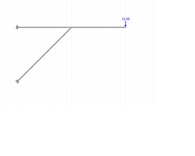
Is there a simple formula for estimating the bending moment and reaction force?

Thanks in advanced!
 
Replies continue below

Recommended for you

I would treat each connection as pinned and then this is just simple statics.
 
If the connections are truly fixed, as shown in your diagram, then the structure is indeterminate and I suggest using a structural analysis program.

If the connections are pinned, it can be solved using statics. There will be a downward reaction of 10 kN at the upper support, and a diagonal reaction of 28.3 kN at the lower support.

DaveAtkins
 
Dave, do you mean an upward reaction at the upper support? it will try to rotate around the diagonal brace.

Let's say each square is 100mm, the maximum moment in the horizontal member will be 10kNm based on the diagonal providing vertical support.

The horizontal tension reaction at the upper support would be 20kN (10kN*2m/1m). Therefore the horizontal compression reaction at the lower support would also be 20kN (therefore the 28.3 kN compression in the diagonal brace). This would all result in a 10kN uplift at the upper support summing the forces in the vertical direction.

Again, assuming it is all pinned. If fixed, then we cannot determine the forces without significantly more analysis.
 
It will be a downward reaction at the upper support, since the horizontal member is trying to rotate around the diagonal brace.

DaveAtkins
 
I'm going to assume we're talking the same thing, one from the side of the beam, and one from the support. To me I would call the connection of the upper beam subjected to an uplift type reaction at the "wall".
 
Thanks for your quick response.

I would like to ask is there is a way to calculate the bending moment? I am selecting steel section for a pipe support and he decision is mainly based on bending moment rather than the axial stress, since section has a much lower bending capacity than the tension/compression capacity. But if all joints are assume to be pinned joint, then the diagonal member would bear no bending. Isn't it not close enough to the real case, which all beams are weld together and moment can be translate though joints? Is there a way to make a rough estimation, or a rule of thumb to make a safe approximation?

There is another concern. If the diagonal is not 45 degree inclined, would it affect the distribution of loading? Should I assume the diagonal section would have a compression of 20/cosθ and find the vertical force in supports accordingly?

Is there any structural analysis program would be suggest to use? I want a more reliable one since I found different program generates different result and I have no idea which one I can trust with.

Thanks a lot!
 
As jayrod12 said in his first post, treat the connections as pinned, and it is simple statics. You don't need a computer program for that.
 
Assume hinges supports and consider benidng moment equilibrium at each hinge, as well as force equilibrium. Simple problem for first-year students!


Jason McKee
proud R&D Manager of
Cross Section Analysis & Design
Software for the structural design of cross sections
Moment Curvature Analysis
Interaction Diagrams
Reinforcement Design etc.
 
Status
Not open for further replies.

Part and Inventory Search

Sponsor