Continue to Site

Eng-Tips is the largest engineering community on the Internet

Intelligent Work Forums for Engineering Professionals

  • Congratulations waross on being selected by the Eng-Tips community for having the most helpful posts in the forums last week. Way to Go!

Basement Wall Bearing Analysis

Status
Not open for further replies.

NRKB17

Structural
Jan 27, 2021
6
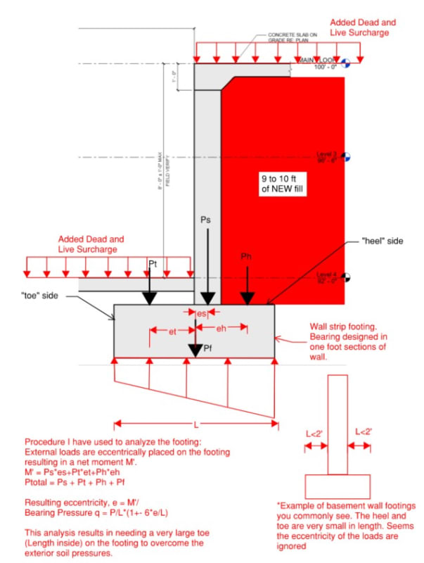
I have a question for you all pertaining to the behavior of the bearing pressure of basement walls that are considered pinned at the top and bottom. Basement walls that I have seen are typically detailed to be supported by a strip footing that extends equally in each direction of the wall to achieve the proper bearing capacity. This creates a concentric load on the footing from the wall. Where I am getting confused is how the soil on the exterior part of the footing is accounted for. To me it seems that there should be a large point load from the soil and possible surcharge on the exterior part of the footing and very little load on the interior part of the footing which is only likely to be a thin slab. To me the footing would then need to be analyzed for the moment that is created with the exterior footing load acting towards the edge of the footing. This creating issues for me though because it is requiring that the footing be extended much further towards the interior to offset this moment. Does any one have any references they can point to for this scenario or offer any advice?

 
Replies continue below

Recommended for you


If the basement wall designed pinned at the top and bottom, there must be main frame with columns etc having spread ftgs. etc..and the basement walls are designed for retaining the soil loads.

This snap from the book ( foundations of structures Clarence DUNHAM )
Notice that, the floors at basement and ground providing lateral support for the basement walls.

basement_wall_nvkyql.jpg


If the basement wall is part of the main force resisting system and continuous footing selected , you should model the wall fixed at the bottom and analyze the ftg similar to the retaining wall base.
 
NRKB17:

I believe your speaking to the actual soil and surcharge pressure being applied to the foundation extension:
Capture_tgsih1.jpg


Technical yes all the loads on the footing should be captured to determine the resultant bearing pressure profile. However it can depend on the context of the allowable bearing pressure you were provided by the Geotech, a net allowable pressure for instance may be the allowable pressure above the existing site soil surcharge pressure at the bearing elevation.

My Personal Open Source Structural Applications:

Open Source Structural GitHub Group:
 
Celt83 what you are showing is what I am referring to. In my condition the soil over the exterior portion is brand new (roughly 9 to 10ft). I also do not have a soils report and am unfortunately held to 1500 psf for my allowable bearing pressure. It just seems analyzing the footing as having eccentric loads on it creates a footing size that appears to very uncommon for restrained basement walls. Are there other assumptions that can be made and if so how are the eccentricities resolved?
BasementWallFootingAnalysis_lhawiz.jpg
 
Couple things

1. The natural overturning point is not where you are taking the moment

2. You are forgetting about that big mass of soil providing lateral restraint via self-weight and surcharge pressure. Your footing cant rotate unless that big mass somehow moves/deflects/crushes

3. Normal forces leading to friction are real even if we ignore them
 
Enable

Can you give a diagram for what you are meaning by your comment in line 2. I am struggling to see what you mean by it. It seems like the large point load that I have labeled Ph does not have anything to resist the moment it creates.

Celt83

An example of the values I have for a 5 foot wide footing ( 3ft toe - inside the basement length, 1' wall thickness, and then a 1 ft heel - outside the basement length) I get the following loads:
Ps = 1.6 kips, Pt = .8 kips, Ph = 1.4kips,Pf = 1.5 kips.

This is resulting in a max bearing of 1934 psf and minimum bearing of 206 psf.
 
I think you need to look at a retaining wall design. See a worked example here where they go through everything you are pondering.

But I would still suggest that the place you are taking a moment about is not the place you want to be taking it from. You should take it about the overturning points to get net bearing to be resisted by the base soil. That would be at the top of the heel/toe at the outermost edges.

Footing_lurbct.png
 
What allowable bearing are you trying to hit?

Increasing the toe length is actually hurting you here because it makes the resultant load have a higher eccentricity from the center of the foundation, increasing the M/S term in the bearing equation.

your Ps is nearly equal to the self weight of just the wall alone are there no other loads on the stem?

Enable:
I believe OP is looking at this wall as a restrained basement wall case in which the lateral earth pressure is taken care of by one-way beam/slab action between assumed lateral restraint at the base and top of the wall.

My Personal Open Source Structural Applications:

Open Source Structural GitHub Group:
 
Enable,

I have the wall considered restrained at the top and bottom so the wall itself is spanning between the footing/low slab and the top slab to act as a simply supported beam. So I am not considering that the footing gets any rotation added from the soil pressure on the wall. As for the rotation I am now looking at the rotation that is exerted on the footing strictly from gravity loads since I am taking the horizontal loads out through the slab at the top and also through the slab at the bottom. This rotation I am finding is the heel wanting to shift down vertically and the toe wants to shift down. I am interpreting that you are looking at this like a cantilevered retaining wall that is causing an overturning moment about the toe that is resisted by the pressure the soil puts vertically on the heel. Is that correct? If so that is not what I am trying to convey. I am also not sure if you maybe are saying instead that if the footing is rotating as I have assumed then the wall will want to move into the soil not allowing the footing to rotate.

BasementWallFootingAnalysis2_dtv8gv.jpg
 
Celt83

I am trying to hit 1500 psf which is turning out to be really difficult without a really big footing. There are no other loads on the stem to help either. The floor above is essentially a slab on grade in a small open warehouse structure so I really only have the self weight of the wall.
 
I may be missing something in this case. But how do you envision bearing failure actually occurring? So it gets overstressed and crushes the soil in vicinity of the heel, what happens? In order for that footing to go anywhere it has to either A) break its connection with the wall, and punch through the slab-on-grade or B) pull the wall down from the slab connection up above + break the SOG or C) have top connection of wall to slab break and crush the soil.

Things cant rotate like you are assuming unless really, really bad things happen at your connections. And at that point, since your connections are severed are we not back at the typical RW case?


NRKB17 said:
The floor above is essentially a slab on grade in a small open warehouse structure..
Oh in that case this is a retaining wall. To design it as a restrained case you need to be able to resist the top and bottom reactions "small open warehouse" says either you won't have enough low slab friction to prevent sliding and/or the the sliding friction resistance of the upper slab on grade is unlikely going to be enough to restrain the top as in my mind the frictional resistance won't start until the edge of the soil failure wedge.


My Personal Open Source Structural Applications:

Open Source Structural GitHub Group:
 
All I am trying to understand is how the basement wall of a house can be designed to have such a small strip footing. I see you are saying the rotation is restrained and the footing can't rotate which results in the uniform bearing pressure underneath the footing. The eccentricity of the loads I have calculated would result in the M' value I have shown above. I am just trying to understand how to resolve the load path for moment with an analysis. Does the moment get decouple in the wall reinforcement in the footing? Does it get resolved in a couple between the low slab and the bottom of footing in friction? I understand the there are elements there that can possibly restrain the footing from rotating I just can't see the load path. Is my confusion clear?
 
NRKB17, I think you are not getting satisfactory answers because you are posing, in my opinion, a novel question for a case that we structural engineers typically ignore. I think it is a decent question. I think the answer to why it is usually ignored, and yet generally does not cause any problems in the real world, is a result of the fact that often times the allowable soil pressure for a basement footing is treated as a net pressure above and beyond the existing soil surcharge, so the weight of the soil over the heel of the footing is ignored. I think this is probably reasonable for many residential basements because they are often excavated into hillsides, etc. However, in your case, you say that it is 10 feet of new fill, so perhaps you are right to consider the weight of the soil on the footing.
 
I agree with gte447f that we generally don't think too much about basement type footing design. Things are generally prescriptive and they just work. That said, I think we can resolve this by usual methods and not necessarily rely on things just redistributing in unknown ways (though I am glad that mechanism exists to save us!)

So attached is a sketch detailing how I am thinking about this. To me, even if you resolve the lateral pressure into pins at the footing elevation / SOG up above, you still have an applied shear component (2/3*W) acting at the top of the footing that needs to be taken into account. This will counteract the moment induced by the eccentric vertical load. My example shows that they net out when taking a moment about the center of the footing at the base.

I am following the usual design criteria of P/A + M/S where the moment is taken about the center of the footing at the base. I believe this is applicable because the net vertical force acts within the middle kern.

One might be tempted to think about the combination of horizontal + vertical loads as an include resultant acting on the footing as described here. This would get you back to the solution provided by the OP (basically neglecting the horizontal component). But I do not think that is appropriate because they are not coincidental.

Am I missing something obvious here? As long at the connection between the footing and the vertical wall is designed for the full eccentric moment induced by the vertical load the footing cannot separate from the wall. Thus treating it as a unit with a restoring lateral load at the base seems appropriate. If the connection is poor, then I agree with the original analysis because the connection will sever and the soil will see the full vertical load. But even there, to overturn there will be a reaction at the toe of the footing against the interior SOG that may provide a restoring moment as well.

I am very willing to accept I am thinking about this all wrong though

Footing_Design_dwewll.png
 
Enable:
Generally if looking at the restrained wall case the wall/foundation joint is not designed for moment transfer only for the shear. The failure depends on what drives the allowable bearing pressure, a settlement based allowable would lead to excessive rotation of the foundation and plastic hinge development at the wall/foundation joint. There will be some inherent rigidity in the joint by nature of the construction so the actual condition will tolerate some redistribution of the soil pressure based on that rigidity, this is how I've seen ignoring the soil/surcharge weights on the extension rationalized.

NRKB17:
for what its worth in my opinion you were following the correct process to solve for the bearing pressure. I also agree that the weights and surcharges on the foundation extensions should be included in the calculation, with exceptions allowed when provided by the Geotechnical engineer.

For this case in particular I would design the wall as a retaining wall as I believe you'll find it hard to develop the required restraining reactions through slab on grade friction.
Capture_ussdf1.png


My Personal Open Source Structural Applications:

Open Source Structural GitHub Group:
 
@Celt83

I did a quick calculation and the reinforcement required to transfer the induced moments at the joint in the OP's configuration is less than the minimum reinforcement by code. So any design will satisfy even if only accidentally.

I suppose it becomes more interesting when minimum reinforcement doesn't provide the necessary resistance. Should it be neglected and left to "other mechanisms"? I mean, bridging of the soil around the footing + shear resistance of the SOG in the vertical sense (at the toe) provide some redundancy. But it probably should not be left and if I am already designing this, and not going prescriptive, then why not add a few extra bars into the joint?

As for why prescriptive walls tend to stay upright even without steel, well that's another matter. But the height restrictions are so limiting that I imagine the low loads + "other mechanisms" works out just fine. Well, it has otherwise it wouldn't be prescriptive!
 
Status
Not open for further replies.

Part and Inventory Search

Sponsor