medeek
Structural
- Mar 16, 2013
- 1,104
Has anyone else had much experience analyzing trusses (metal plate connected trusses) utilizing RISA3D?
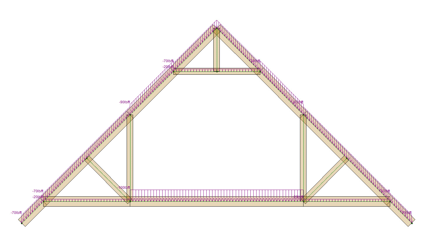
I've pin jointed all of the web members and rigid jointed the heel and peak joints. For now I've ignored all of the load cases and just assumed one load case to get a better feel for the Axial, Shear and Moments in the various chords and webs.
Loads
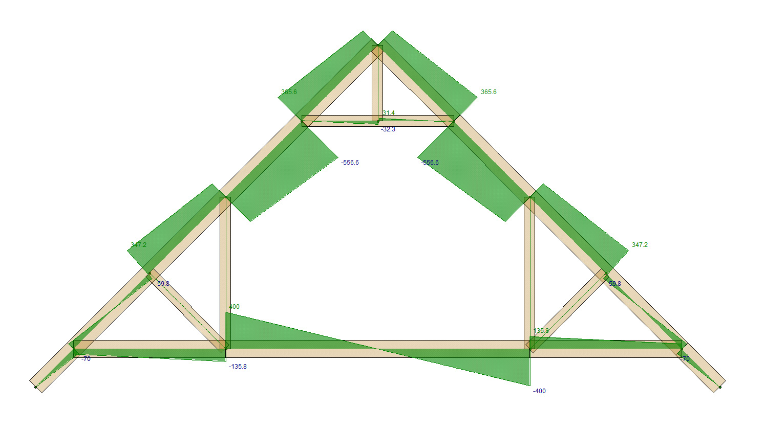
Axial

Shear
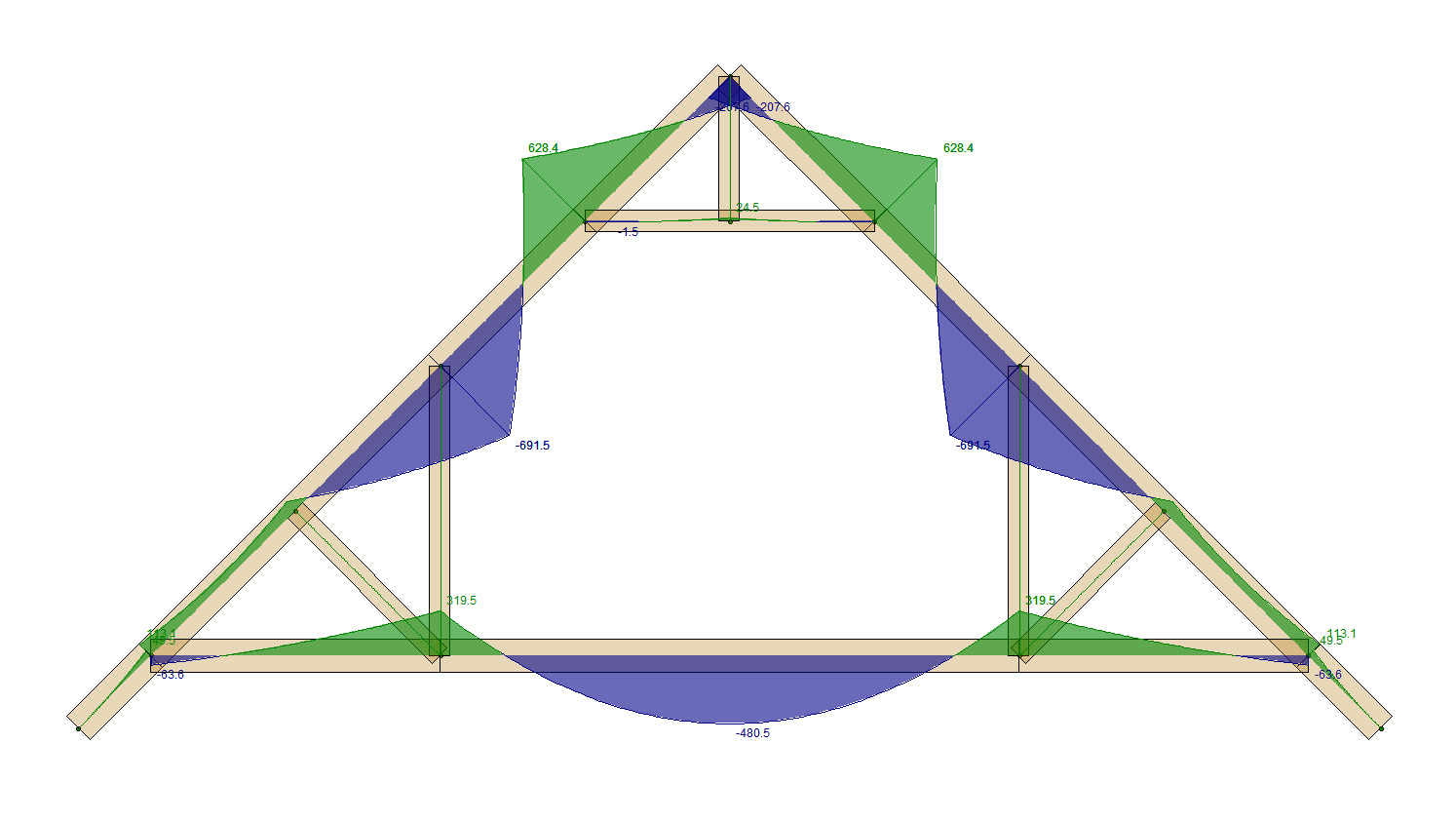
Moments
A confused student is a good student.
Nathaniel P. Wilkerson, PE
I've pin jointed all of the web members and rigid jointed the heel and peak joints. For now I've ignored all of the load cases and just assumed one load case to get a better feel for the Axial, Shear and Moments in the various chords and webs.
Loads
Axial
Shear
Moments
A confused student is a good student.
Nathaniel P. Wilkerson, PE


