Continue to Site

Eng-Tips is the largest engineering community on the Internet

Intelligent Work Forums for Engineering Professionals

  • Congratulations waross on being selected by the Eng-Tips community for having the most helpful posts in the forums last week. Way to Go!

ASCE 113 Base Plate Design - Calculating effective length of bend line 1

Status
Not open for further replies.

SUB23

Civil/Environmental
Feb 28, 2020
5
I have a question regarding ASCE 113’s base plate design. How do you go about calculating the effective length of the bend line (beff)? On page 103 of the 113 manual, a brief method for finding beff is given – “(beff) is assumed to be limited by the distance between the projected length of the first and last bolt acting on the bend line plus the sum of the perpendicular distances from these extreme bolts to the bend line.” So if I have a 4 bolt pattern at 12”x12” and I am using an HSS8x8 column I would have the following effective bend line length for the bend lines at the faces of the column...

beff = 12”(projected length of the first and last bolt acting on the bend line) + 2*2”(sum of the perpendicular distances from these extreme bolts to the bend line) = 16”

However, how would I calculate the beff for the “diagonal” bend line across the corner of the column? Since there is only one bolt acting on that bend line, would I just use 2 times the perpendicular distance from that bolt to the bend line? So in my case above, beff = 2*(sqrt(2)*2”), which seems very small.

Thanks!
 
Replies continue below

Recommended for you

Are you talking about "checking bending in one corner of the base plate", or the bending diagonally across the base plate from corner to corner? Two different measures.
 
@retired13
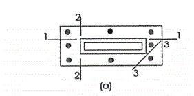
The bend line in one corner of the base plate - tangent to the corner of the column. See bend line 3 in attached picture for clarification.


Corner_bend_line_nueqxn.gif
 
Also, here is the section of 113 I am referring to.....


beff_ed8b55.gif
 
Ok. My method may not be exact, or even correct, but I usually take a line from edge to edge that connect the bolt in the middle. I consider it is simple and conservative.
 
@retired13

So for my given example, you would use the following as the effective bend length?

1_qgnb8j.gif


For this particular case, it comes out the same as 2 times the perpendicular distance from that bolt to the bend line. (Assuming a 16"x16" base plate which I would typically use for a 12x12 bolt pattern)
 
Yes, that's what I meant.
 
Note, another potential weak plan is at a line thru the corner of the column. I think you can check with a line at a distance dp away from that line. dp is the thickness of the base plate.
 
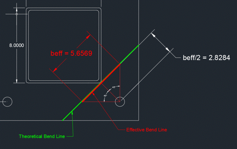
Aren't they talking about where the projected distance hits the bend line? I visualize more like this.

beff_yhqsdm.png
 
@azcats

That is what I took it to mean. So for the case where only one bolt acts on the corner bend line, it comes out to be 2 times the perpendicular distance from the bolt to the bend line.

2_u26wqw.gif


ASCE/SEI 48-05 uses this 45 degree method for developing the effective bend line length.
 
I need to check into it as your sketch indicated. My thinking is the stress is highest right on the corner of the column, however, the entire section is engaged to resist the bending due to consistence in deformed shape. The dp suggestion is based on the AISC provision for checking column base plate.
 
We are currently revising 113 and will have some new equations for thickness of base plates. It will also recommend that you consider bolt bending if the plates are on leveling nuts. The beff limit at 45° that ASCE 48 uses is probably conservative. I have used 12 times thickness for a single corner bolt for many years and IIRC it is in 113 around this section somewhere and came from the Omer Blodgett book. The problem comes on a small square tube when the hole in the base plate is the same size as the tube and you fillet weld around the tube to allow for galvanizing flow. In this case the tube wall can't handle the bending and the beff is from the corner to the plate edge as shown in bend plane 2-2 of the figure.

What was intended to design the base plate thickness was to find each bolt load and sum moments about the assumed bend line which is limited by beff. In our typical substation structures which have a very high moment load at the base plate, one of the bolts will have the high load and you find the plate thickness for the bending moment on all the assumed bend lines and pick the thickest plate.

_____________________________________
I have been called "A storehouse of worthless information" many times.
 
Status
Not open for further replies.

Part and Inventory Search

Sponsor