Continue to Site

Eng-Tips is the largest engineering community on the Internet

Intelligent Work Forums for Engineering Professionals

  • Congratulations cowski on being selected by the Eng-Tips community for having the most helpful posts in the forums last week. Way to Go!

AS4100/NZS3404 use of alternative design provisions for combined actions

Status
Not open for further replies.

Agent666

Structural
Jul 2, 2008
3,080
What are peoples thoughts on this situation:-

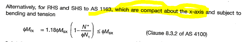
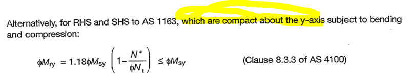
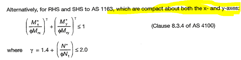
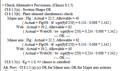
Both AS & NZ steel standards allow the use of alternative design provisions for combined actions, i.e. if section is compact, is a doubly symmetric I section or a square hollow section alternative equations can be used in chapter 8. NZ code has some further qualifying provisions for applying these alternative provisions on top of the smaller subset of requirements in AS4100. These relate to alternative slenderness requirements and axial load limits but are not important with regard to the intent of this query.

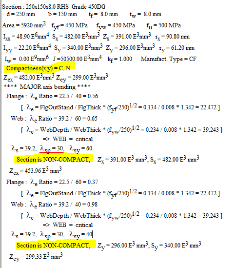
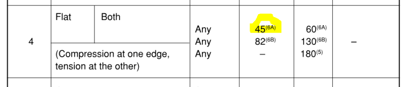
I was wondering what peoples interpretation of 'compactness' is in terms of application of these provisions, say we have the situation whereby a rectangular hollow section is compact about major axis but non-compact or even slender about the minor axis.

1. If section is subject to only major axis bending then you'd only need to be compact about this axis to use the alternative provisions, so our example RHS would satisfy this requirement?

2. If section is subject to only minor axis bending then I'd say you cannot use the alternative design provisions as you are not compact about this axis. This aspect seems clear to me as the intent of the standards.

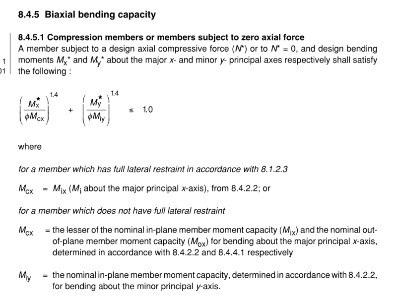
3. If section is subject to biaxial bending then you'd need to be compact about both axes to use the alternative provisions.

4. Or would you only apply the alternative design provisions if the section was compact about both axes even if there was only uniaxial bending?

Keep in mind the alternative provisions are a means of allowing for more capacity due to allowing some yielding and inelastic action within the cross section provided it doesn't impact on member stability and the like. So it makes sense to me at least that you should only need to consider the compactness about the axis of loading to achieve this increase as element slenderness is satisfied about that axis?

Any agreement/disagreement/comments with this approach?

I have not been able to find anything which states definitely one way or the other if a single axis of being compact is ok vs requiring both to correctly apply these provisions.

Thanks
 
Replies continue below

Recommended for you

Depends on whether you have compression over the full width of the element or whether it goes into tension over part per table 5.2. If assessing case by case isn't practical and there is significant minor axis bending rather than nominal/ incidental, the conservative route would be requiring the uniform compression slenderness be satisfied for both.
 
Thanks for the reply, compactness is evaluated based on bending stress distribution (at least in NZ standard), and is evaluated for each direction separately. That's easy in the scheme of things, but not really related to what I was actually asking.

Fyi, in NZ standard to use the alternative provisions we need to also have k_f =1.0, this takes care of the compression load slenderness and is one of the additional things we need to satisfy compared to AS4100. Don't believe there is anything similar in AS standard as far as I can tell.

The thing is using the alternative provisions can result in a huge capacity increase, so if the conservative approach had a few percent in it I wouldn't worry about it. But if the difference is 40% which it can be then I want to ensure it can be taken. Whether you just need a compact section about the same axis as load or both becomes important. Any comments on this aspect?
 
Where does NZS say to do it about the axes separately? I want to check corresponding AS clause.

I take the requirement as applying to the resultant stress distribution (N + Mx + My), so there is no major axis slenderness or minor axis slenderness, just section slenderness which depends on loading (ie not an inherent section property).

kf=1 requirement is in AS too for higher-tier member capacity.
 
I guess it doesn't say it explicitly, but it's implied because using the provisions you can determine a different compactness for flexure about each axis (most notably for RHS as noted in original post), all section tables by ASI for example list the compactness about each axis separately as well.

The intent is the slenderness provisions are evaluated separately for moment and compression. In the case of moment to work out effective section modulus to section 5, and for compression to work out effective area and hence k_f factor from section 6. Though the compactness (C, N, S) is simply related to the 'moment' slenderness evaluation related to determining effective section modulus.

Interesting if you interpret it that way or have been taught to do it that way, but you definitely don't do it the way you noted based on the final stress distribution. These calculated properties (Z_ex, Z_ey anf k_f) are an 'inherent section property', any interaction from flexure and axial loads are simply dealt with via the combined actions checks, not via calculating loading specific fundamental section properties. This is the way its implemented, and taught in NZ.

There are separate slenderness tables for moment, and compression in NZ standard (and different ones again for seismic classification of the cross section just to be difficult!). Pretty sure As4100 has similar separate limits (will need to check).

Do you have a clause for the higher-tier member capacity thing you mentioned? (never heard that term before, must be specific to AS standard)
 
[Preliminaries:
Higher tier = alternative provision.
I say that Ze is loading dependent because it is for monosymmetric/unsymmetric sections (see the tables for channels and angles for example), but not for the doubly-symmetric sections under discussion here.]

The more I use standards, the more I realise they are written around the most common situations, with a few bolt-ons for other common (but less so) situations, and need some interpretation (or are flat out wrong) for other situations like you found the other week with the monosymmetric kt factor question. For AS4100, I think the base case is BHP I-sections (doubly symmetric). If I've counted correctly, only three of the standard I-sections (WC, WB, UC, UB, TFB, UBP) have different X & Y slenderness categorisation - all three are WBs. When AS4100 was written and grade 250 was the standard, perhaps even these weren't exceptions. So it doesn't surprise me that the standard doesn't clearly spell out which axis in the alternative provisions because it doesn't matter if you're only thinking about the I-sections and not the RHS sections.

As for taking the total stress state for checking slenderness vs separately checking Mx, My & N, I think we could concoct unsatisfactory situations for either case since they're highly simplified checks. I had hoped to find time to check whether my suspicion that a slender section but with no compressive stress (axial tension plus small moment) would still end up having capacity reduced for local buckling if the moment were treated separately. But not enough time...

In a similar vein, there must be some threshold below which the minor axis moment on the X-compact/Y-slender RHS has negligible effect and the alternative provision capacity is still valid. Does M*y = 1% of phi.Msy (~3 MPa) mean we have to give away the 18% capacity increase? This probably exists in real structures due to tolerances and compatibility rotations but we ignore it.

Having made you read all that, I've found that the AISC Design Capacity Tables for Open Sections (I have 1999 version) explicitly use #1 from your original post rather than #4.
 
I say that Ze is loading dependent because it is for monosymmetric/unsymmetric sections (see the tables for channels and angles for example), but not for the doubly-symmetric sections under discussion here.
They are load direction dependant, as in positive or negative flexure. I don't agree that these effective properties are dependant on final stress state (flexure + bending). The intent of the standard is that the determination of Ze is based on bending stress distribution in isolation, and kf is based on axial compression stress distribution in isolation.

Any non doubly-symmetric sections is going to have two values as under one direction of bending a different part of the section is in compression for evaluating the plate slenderness provisions than the other direction (i.e. channels are probably the best tabulated examples of this or custom designed mono-symmetric beams).

the more I realise they are written around the most common situations
Don't disagree with this, often there are holes for fringe cases. If you're implementing something in software (the basis for the question) then you find these fringe cases all the time, the "what if you have this, how do with deal with it" type situations. Sometimes the intent of the code isn't wholly exposed the reader to distinguish the best or accepted way forward.

So it doesn't surprise me that the standard doesn't clearly spell out which axis in the alternative provisions because it doesn't matter if you're only thinking about the I-sections and not the RHS sections.
Well it surprises me, because many of the alternative design provisions are directly related to hollow sections. These are the most likely sections to have different compactness about principle axes. Agree that for I-sections it barely makes a difference based on the standard rolled sections, but for custom welded sections you can start to get into this (for example thin webs about y axis with heavier flange might be compact about y axis, but for x axis they are non-compact governed by web slenderness.

In a similar vein, there must be some threshold below which the minor axis moment on the X-compact/Y-slender RHS has negligible effect and the alternative provision capacity is still valid. Does M*y = 1% of phi.Msy (~3 MPa) mean we have to give away the 18% capacity increase? This probably exists in real structures due to tolerances and compatibility rotations but we ignore it.
In NZS3404 we have some significant axial force provisions, if the axial load is under these and you meet some other criteria then we don't even need to check combined actions for axial + bending. Similarly for such a small moment when you get into the biaxial checks it barely makes a difference in practice (especially so if you are able to use the alternative provisions with the ratio M*/ΦM raised to the power of 1.4). From what I looked at in AS4100 you do not have similar minimum axial load provisions for applying combined actions that I could see, and quite a few of the alternative provisions take a different form in the equations in NZS3404.

In some cases checking the provisions to assess if the axial force is significant, or if the alternative provisions can be used is more work than just simply checking the combined actions in the first place. So I'm sure we could have further checks to check if the small moment is insignificant and can be ignored, but the code writers would probably make that more complicated than just checking the case with the small y moment.

Interestingly when I started out down the path of writing all the checks into some python code I was under the impression that AS4100 and NZS3404 approaches were going to be more or less the same except for the addition of some earthquake stuff in NZ code. But the more I get into it there seems to be a lot of differences in the stuff I'd always thought was the same. Don't get me wrong, 95% is word for word the same, but obviously with the seismic thing in NZ there warranted some differences obviously, and there are a few other things that have feed into our standard over time base don research that has meant they have diverged slightly in some aspects. The code I am producing (which I will open source when complete) I was hoping would be able to do both standards with little effort, but this would require quite a bit more work to separate it into NZ and AS stuff now that I'm into it.

I've found that the AISC Design Capacity Tables for Open Sections ....
Thanks for that, I'll take a look at the closed sections and open sections versions and see if its definitive.
 
I think looking through the ASI tables, and the examples given there it's pretty definitive that to apply alternative provisions you need to be compact about the axis of bending. Or for biaxial alternative provisions compact about both axes. For biaxial if you only have compact section about one axes, then you use the normal biaxial check, but you can still use the alternative ΦMry or ΦMrx provision about that one axis (the nomenclature is slightly different between AS and NZ standards, but the intent is the same). In the normal provision you don't have the 1.4+ power, its just a linear relationship, but you are still taking advantage of the increase in capacity about that one axis by being able to use the alternative capacity which answers your point below I guess:-

In a similar vein, there must be some threshold below which the minor axis moment on the X-compact/Y-slender RHS has negligible effect and the alternative provision capacity is still valid. Does M*y = 1% of phi.Msy (~3 MPa) mean we have to give away the 18% capacity increase? This probably exists in real structures due to tolerances and compatibility rotations but we ignore it.


Thanks for the lead on that, confirms my original thinking.

i.e. for RHS hollow sections:-
1_ymk5ex.png

2_hnga5t.png

3_vvahtl.png
 
How is NZS 8.1.5(b)(ii) applied? Is it the combined stresses given it's in the combined actions section or by individual Mx, My and N action since it refers to section 5?

Agent666 said:
For biaxial if you only have compact section about one axes, then you use the normal biaxial check, but you can still use the alternative ΦMry or ΦMrx provision about that one axis (the nomenclature is slightly different between AS and NZ standards, but the intent is the same). In the normal provision you don't have the 1.4+ power, its just a linear relationship, but you are still taking advantage of the increase in capacity about that one axis by being able to use the alternative capacity which answers your point below I guess

The normal biaxial section check in 8.3.4.1 reverts to section capacity Msx instead of Mrx. So N*=20% of capacity plus M*x=94% is ok using uniaxial alt provision. Add 1% of M*y (Y-slender) and it becomes available 15% over?

 
Regarding 8.1.5(b)(ii), you can apply these limits in accordance with 5.2.2.1 as noted, i.e. using bending stress distribution similar to how you evaluate Z_e. For major axis I section, flange in uniform compression (case 1 table 8.1), web in compression one edge tension at the other edge (case 4, table 8.1), etc.

The alternative provisions are based on recognising significant cross section ductility can occur along the member without member failure or localised section failure. This is achieved based on there being acceptable limits on local buckling of plates based on achieving the relevant slenderness limits. This is why this clause notes the limits are based on Category 3 member limits, see note 3 at bottom of table 8.1 referenced. Category 3 member is termed nominally ductile, basically some limited inelastic action and limited plastic rotation at any of these hinges.

The normal biaxial section check in 8.3.4.1 reverts to section capacity Msx instead of Mrx.

Agree for section check. , I was more referring to the member biaxial check specifically, because this is where its different and you can use Mrx (this clause basically from NZS3404), Mrx cannot be greater than Msx for obvious reasons:-
4_svqerr.png


Mox here is basically Mrx from AS code (evaluated to alternative provisions if you satisfy all of the requirements of 8.1.5), this is where the nomenclature and subscripts changes between codes, but like I noted the intent is the same I believe.

I'll have a think a bit more about the last sentence and get back here if I think of anything else, but have the following initial comments:-
If you are slender though basically you cannot get the ductility about that axis, then it doesn't work for the section check at that location (your 15% over). But for the member check you can rely on the enhancement about the single axis.

After all 8.3.1 & specifically 8.3.1(c) says for biaxial bending all you need to satisfy is the biaxial check, you work out the other values along the way though, so in case of not meeting alternative provisions about 1 axis then for section check you use the non alternative provision. Similar applies in reading 8.4.1 & specifically 8.4.1(c) regarding member check.

For section check, every station along a member needs to satisfy the inequality, but for member check its one check for the entire member based on maximum loads. Maximum loads don't need to coincide with respect to location, it's more about combined effect of member buckling and/or remaining stable.

I feel you cannot work in terms of percentages, because alternative provisions are not linear, something that is 20% over is simply a fail, you cannot imply some stress is 20% higher.

So comparing percentages are like comparing apples to oranges. Really need some actual real capacities to demonstrate effect I guess.

You have to remember the uniaxial check already included the axial load reduction to moment capacity as well, so again cannot compare directly percentages when the other section check is based on Msx/Msy. See point above about the only check really needed is the biaxial check as this encompasess everything.
 
The alternative provisions aren't linear but the lower tier pretty much is. I've concocted this example:

250x150x8 RHS gr.450
N*=480 kN (20%)
M*x = 183 kNm (94%)
Alternative provision section check passes.

Now add M*y = 1 kNm. Can no longer use alternative provision section check as slender for M*y. Increase to 9mm wall thickness but still fail lower tier check so need 10mm wall (23% weight increase). Or do you use judgment to ignore M*y? If so, what is the threshold?

I'm also hung up on reducing capacity for slenderness when the entire section is in (varying) tension. Is this a real phenomenon?
 
Looking at your example in MEMDES which is a common program for checking steel in NZ, it notes in checking to section 5 limits the 250x150x8 G450 section is non-compact about both axes (web critical). 250x150x9 & 250x150x10 are also non-compact about both axes. Though I'm not convinced they actually have it correct as they get some funny numbers to be honest when checking to section 5 (need to look into it further). Checking the 8.1.5(c)(ii) requirements are satisfied though, even for the 250x150x8 section about both axes, this allows the use of alternative provisions about both axes. When you drop to 6mm wall thickness you start to get one axis satisfying the 8.1.5(c)(ii) check and the other not satisfying (need to digest what path they take beyond this point for the combined actions checks).

Note that we have slightly different slenderness values for hollow sections and webs of I-sections which may help explain the differences if you are using some software to come up with your comparison when assessing compactness to section 5.

The problem is MEMDES doesn't check all requirements for some of the checks required, sometimes it warns you about certain things, other times there is no warning (if you read the manual it highlights some of the things it assumes/does not check). This was part of the impetus for coding up the checks in python, as some of the things really need to be checked and people weren't/don't do it in practice.

Or do you use judgment to ignore M*y? If so, what is the threshold?
Million dollar question I guess, totally see where you are coming from, but going back to first principles, if you get local plate buckling about the y direction then it's all over as far as the code is concerned. The buckling completely destabilises the entire plate element. Codes are fairly binary, they need to be I guess.

I'm also hung up on reducing capacity for slenderness when the entire section is in (varying) tension. Is this a real phenomenon?
If a plate element is in tension (like tension flange in I-Section) then it cannot buckle/not subject to local buckling. Combined actions section checks with section in tension always use ΦMsx, this by its nature includes the slenderness reductions obviously (which I agree could be counterintuitive with large tension and small bending resulting in full cross section being in tension). I guess this is simply a by product of one design rule to cover all situations, simplicity and conservatism wins over evaluating things 15 different ways for small benefit.
 
The AusTube Mills tables say that 250x150x8/9/10 are all X-compact/Y-noncompact. I just took their word for it and did calcs on the back of an envelope. And yes, I did cherry pick the only case where 1% of M*y requires two steps up in wall thickness.

Posting on a forum is one thing but real design is another. I wouldn't be as aggressive as in my first post. Probably look at how close to the major-axis compactness limit a section's web is to guide how much of the minor axis moment can be tolerated in a Y-noncompact section whilst still using the alternative provision. And only if there were some benefit without great risk.

I look forward to any other fringe cases your python quest throws up. They're educational. Are you going to sell the python checking software?
 
Nah just going to open source it if I can get it to a point where it is relatively easy to use for someone who is familiar with the standard. People can do what they want with it is the current plan. Last thing I want is to release something that is essentially command line only that is so complicated people won't potentially use it correctly. Eventually I was hoping to make a GUI for it.

The AusTube Mills tables say that 250x150x8/9/10 are all X-compact/Y-noncompact.
Yeah that's the thing, in MEMDES it initially lists it as X-compact/Y-noncompact which is why I was saying the numbers were a bit screwy (see output below), but then when it actually checks it they come up with non compact about both axes. I suspect I've found an error in the program though, looking at the red underlined value it should actually be 45 as per table 5.2 of NZS3404 for 'web' x axis bending (i.e. case 4 from table 5.2). If 45 is used then its compact.

Note in AS4100 the limit is 82/115 for case 4, but in NZ for webs of hollow sections its 45/60. I remember at the time they amended this they mentioned it was due to seismic concerns, cyclic loading causing local buckling at a ratio of 82 based on experiments/research, etc. So limits were tightened up considerably, previously they were 82/130 pre-amendment for both hollow and I-sections (so different from AS standard of 82/115).

1_wqfvxa.png

2_iqdjwx.png


I remember years ago AustTube Mills (used to be Smorgon Steel from memory) used to have separate NZ and Aust property tables for the reason of the different slenderness ratios for the webs. I've never seen these hollow sections in NZ though. I guess you can indent them, but unless you need hundreds of meters of section it's not even a practical option to use them.
 
Note that for use of alternative provisions using table 8.1 that the limit is still 82 for the web, therefore the 250x150x8 section with a ratio of 39.2 would still be classified as "compact" using 8.1.5(b)(ii) for application of applying combined actions checks with the alternative provisions. Pretty confusing!

3_yifqj9.png
 
Status
Not open for further replies.

Part and Inventory Search

Sponsor