Hi everyone,
hope someone will help me beacause it's weeks since I'm trying to solve this problem without any sucsess and I'm quite frustrated, I'll be grateful for any kind of tips . I would like to simulate this process using LINK180 elements:
In order to have an idea of cables behaviour I read manuals and I've also seen examples present on the Verification Manual by ANSYS (where it is said that if you want to use LINK180 elements for cables you have to give them an initial small strain with INISTATE command and you'll have an initial system stiffness different from 0).
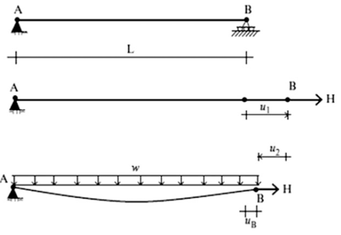
Aware that in the case of the picture I would get a parabola deformed shape, while if the load were applied along the lenght of the cable I get a catenary shape, these are my data:
final chord=L+u_b=304.8 m ; L+u1=312.73m (length of the cable after pretensioning)
E=131 000 N/mm^2 ; w=46.12 N/m ; A=548.4 mm^2
attended sag = f =30.48 m (got from a paper)
The value of H is set in order to get a specific sag around f, so H=17.57 kN (I got this value from parabola formulas, the catenary ones would have gave me H=18 kN, so there is no a big difference).
Initially I want to study a simple model, so I divided the cable in 10 elements, then applied the pre-tensionig force H (that I think is equivalent of using INISTATE command) and then, using a nonlinear analysis, I applied the dead load F at each node of the cable in a way that F*10=w*L
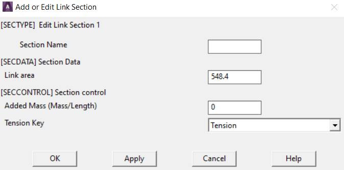
Then, as I'm working with cables, I set that they can resist only against tensile forces:
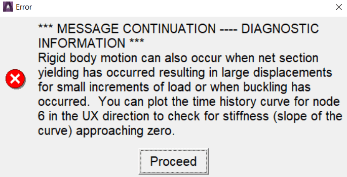
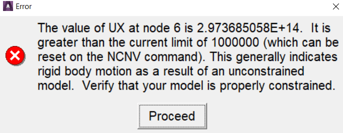
Then I set the nonlinear analisys (Automatic time stepping, ON; Line search ON (the manual says it is useful for flimsy structures); NEQIT=1700 ) but when I ask the software to solve it says the model is unconstrained:
Then, if I try to set tension key on tension and compression,the program runs and numerical sag not only is plausible but also, if I augment the elements (10,100,1000,4000,6000), it converges to the value typic of the catenary (34.0m ; 31.1m ; 30.9m ; 30.84m ;30.84m vs. 30.86 ). That is even more correct than the 30.48 attended sag that corresponds to a parabola shape.
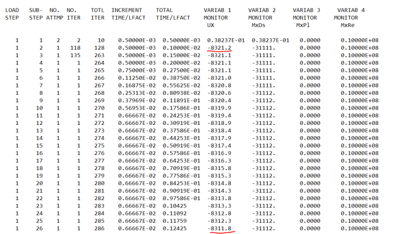
Remaining on tension-compression case, if I monitor UX displacement of one node (for example the 11th, last one) it seems that it initially goes immediatly left and then move slightly right while I thaught that they will only move left... I suppose that elements first go on compression and then in tension but this is not right.
Here's a screen of UX displacement of 11th node (where there's the roller) in wich I see that the displacement is decreasing in modulus instead of increasing and it makes no sense altough the final UX displacment (8244.8 mm) gives L+u1-UX=312.65m (initial cable length set in order to have a tensionend length of 312.73) + 0.0764m (due to pretensioning) - 8.244m = 304.48 that is exactly L+u_b=304.48 m
Moreover, in only-tension case (10 elements) if I augment H of 1 order of magnitude (i.e 175.7 kN) I get a sag that is 3.5 m that is numerically similar to 34.0 m obtained in tension-compression case.
I'm really confused, hope my problem is enough clear and grateful to anyone could help me !
I leave the input file right here :
!-----SET STRUCUTRAL ANALYSIS------!
/PREP7 !structural analysis
/NOPR
KEYW,PR_SET,1
KEYW,PR_STRUC,1
KEYW,PR_THERM,0
KEYW,PR_FLUID,0
KEYW,PR_MULTI,0
FINISH
!-----ELEMENT TYPE, CROSS SECTIONAL AREA, MATERIAL-----!
/PREP7
ET,1,LINK180
SECTYPE,1,LINK
SECDATA,548.4
SECCONTROL,0,1 ! only tension
MP,EX,1,131000
!-----DEFINE NODES AND ELEMENT-----!
N,1
N,11,312653 ! initial length of the cable set to 312.65m in order to get a final lenght of the tensioned cable about 312.73 m
FILL
E,1,2
EGEN,10,1,1
!-----BOUNDARY CONDITIONS and PRETENSIONING FORCE-----!
D,1,ALL
D,2,UY,,,11
D,ALL,UZ
F,11,FX,17570 ! H=17.57 kN
FINISH
!----SOLVE CABLE PRETENSIONING-----!
/SOLU
SOLVE
FINISH
!-----DELETING SUPPORTING HINGES AND APPLY DEAD LOAD-----!
/PREP7
FLST,2,9,1,ORDE,2
FITEM,2,2
FITEM,2,-10
DDELE,P51X,UY
FLST,2,11,1,ORDE,2
FITEM,2,1
FITEM,2,-11
F,P51X,FY,-1602.73
FLST,2,2,1,ORDE,2
FITEM,2,1
FITEM,2,11
FDELE,P51X,FY
FINISH
!----ITERATIVE SOLUTION----!
/SOL
NLGEOM,ON
AUTOTS,ON
NSUBST,500,1000,150
OUTRES,ERASE
OUTRES,ALL,ALL
NCNV,2,0,0,0,0
TIME,1
NEQIT, 1700, !high number of equilibrium iteration in order to get convergence also for higher substeb
LNSRCH, ON, , !activate line search as said in ANSYS manual
CNVTOL, F, , 0.001, 2, !convergence set on forces and displacemente
CNVTOL, U, , 0.001, 2,
hope someone will help me beacause it's weeks since I'm trying to solve this problem without any sucsess and I'm quite frustrated, I'll be grateful for any kind of tips . I would like to simulate this process using LINK180 elements:
In order to have an idea of cables behaviour I read manuals and I've also seen examples present on the Verification Manual by ANSYS (where it is said that if you want to use LINK180 elements for cables you have to give them an initial small strain with INISTATE command and you'll have an initial system stiffness different from 0).
Aware that in the case of the picture I would get a parabola deformed shape, while if the load were applied along the lenght of the cable I get a catenary shape, these are my data:
final chord=L+u_b=304.8 m ; L+u1=312.73m (length of the cable after pretensioning)
E=131 000 N/mm^2 ; w=46.12 N/m ; A=548.4 mm^2
attended sag = f =30.48 m (got from a paper)
The value of H is set in order to get a specific sag around f, so H=17.57 kN (I got this value from parabola formulas, the catenary ones would have gave me H=18 kN, so there is no a big difference).
Initially I want to study a simple model, so I divided the cable in 10 elements, then applied the pre-tensionig force H (that I think is equivalent of using INISTATE command) and then, using a nonlinear analysis, I applied the dead load F at each node of the cable in a way that F*10=w*L
Then, as I'm working with cables, I set that they can resist only against tensile forces:
Then I set the nonlinear analisys (Automatic time stepping, ON; Line search ON (the manual says it is useful for flimsy structures); NEQIT=1700 ) but when I ask the software to solve it says the model is unconstrained:
Then, if I try to set tension key on tension and compression,the program runs and numerical sag not only is plausible but also, if I augment the elements (10,100,1000,4000,6000), it converges to the value typic of the catenary (34.0m ; 31.1m ; 30.9m ; 30.84m ;30.84m vs. 30.86 ). That is even more correct than the 30.48 attended sag that corresponds to a parabola shape.
Remaining on tension-compression case, if I monitor UX displacement of one node (for example the 11th, last one) it seems that it initially goes immediatly left and then move slightly right while I thaught that they will only move left... I suppose that elements first go on compression and then in tension but this is not right.
Here's a screen of UX displacement of 11th node (where there's the roller) in wich I see that the displacement is decreasing in modulus instead of increasing and it makes no sense altough the final UX displacment (8244.8 mm) gives L+u1-UX=312.65m (initial cable length set in order to have a tensionend length of 312.73) + 0.0764m (due to pretensioning) - 8.244m = 304.48 that is exactly L+u_b=304.48 m
Moreover, in only-tension case (10 elements) if I augment H of 1 order of magnitude (i.e 175.7 kN) I get a sag that is 3.5 m that is numerically similar to 34.0 m obtained in tension-compression case.
I'm really confused, hope my problem is enough clear and grateful to anyone could help me !
I leave the input file right here :
!-----SET STRUCUTRAL ANALYSIS------!
/PREP7 !structural analysis
/NOPR
KEYW,PR_SET,1
KEYW,PR_STRUC,1
KEYW,PR_THERM,0
KEYW,PR_FLUID,0
KEYW,PR_MULTI,0
FINISH
!-----ELEMENT TYPE, CROSS SECTIONAL AREA, MATERIAL-----!
/PREP7
ET,1,LINK180
SECTYPE,1,LINK
SECDATA,548.4
SECCONTROL,0,1 ! only tension
MP,EX,1,131000
!-----DEFINE NODES AND ELEMENT-----!
N,1
N,11,312653 ! initial length of the cable set to 312.65m in order to get a final lenght of the tensioned cable about 312.73 m
FILL
E,1,2
EGEN,10,1,1
!-----BOUNDARY CONDITIONS and PRETENSIONING FORCE-----!
D,1,ALL
D,2,UY,,,11
D,ALL,UZ
F,11,FX,17570 ! H=17.57 kN
FINISH
!----SOLVE CABLE PRETENSIONING-----!
/SOLU
SOLVE
FINISH
!-----DELETING SUPPORTING HINGES AND APPLY DEAD LOAD-----!
/PREP7
FLST,2,9,1,ORDE,2
FITEM,2,2
FITEM,2,-10
DDELE,P51X,UY
FLST,2,11,1,ORDE,2
FITEM,2,1
FITEM,2,-11
F,P51X,FY,-1602.73
FLST,2,2,1,ORDE,2
FITEM,2,1
FITEM,2,11
FDELE,P51X,FY
FINISH
!----ITERATIVE SOLUTION----!
/SOL
NLGEOM,ON
AUTOTS,ON
NSUBST,500,1000,150
OUTRES,ERASE
OUTRES,ALL,ALL
NCNV,2,0,0,0,0
TIME,1
NEQIT, 1700, !high number of equilibrium iteration in order to get convergence also for higher substeb
LNSRCH, ON, , !activate line search as said in ANSYS manual
CNVTOL, F, , 0.001, 2, !convergence set on forces and displacemente
CNVTOL, U, , 0.001, 2,