Continue to Site

Eng-Tips is the largest engineering community on the Internet

Intelligent Work Forums for Engineering Professionals

  • Congratulations cowski on being selected by the Eng-Tips community for having the most helpful posts in the forums last week. Way to Go!

anchored bottom chord extension 2

Status
Not open for further replies.

kipfoot

Structural
Oct 25, 2007
493
I was contacted to evaluate a dumb detail condition where steel angles have puled away from the block wall.

It's a roof system with open web steel joists supported by a concrete block wall. The joist bottom chords are welded to the steel angles, which are fastened to the block with 1/4" expansion anchors. The joists span about 42' and the masonry wall is approx. 26' from the slab to the underside of deck. I think this building is about 20 years old. This is mid-atlantic USA: hot summers, mild but below freezing winters.

The angles seem to have pulled away from the wall, 1/2" in the worst case, causing the anchors to fail and spall the face of block. I'm hoping you'll have some guesses about what might have led to this condition. On the attachment I'm showing the detail as it exists and a few photos.

Possibilities I'm thinking:
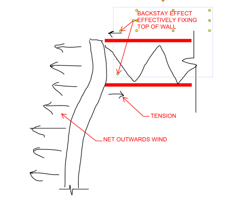
-uplift on the trusses? I'd expect the bottom chord to push out on the wall with this detail, but this seems to have pulled inward.
-movement of the wall? It's ridiculously tall for an 8" block + 4" brick in my opinion, but I wouldn't expect this movement near the top.
-temperature movement? Maybe it was a hot summer day when the weld was placed.

I haven't done calculations to test these ideas. I don't know if this is a recent occurrence or if someone only recently noticed or decided to call someone. There's also moisture in the masonry, causing blistering of the interior paint.
 
 https://files.engineering.com/getfile.aspx?folder=eea9b361-9241-404f-a475-163277d7fe0c&file=bottom_chord_extension.pdf
Replies continue below

Recommended for you

Kipfoot:
The fact is that the bot. chord and attachment angle may also have punched into the conc. blk. wall, and caused much of the initial damage. In effect, they produced/caused an unintended fixed end moment btwn. the top chord and the bot. chord on those stl. jsts. Once the A.B. connection has been broken, there can be some movement in any direction. The stl. jst. people usually want to know when you are going to do this to their jsts. because they usually don’t design for the possible jst. loads/forces/stresses induced by this condition. These loadings could also cause some bending perpendicular to the plane of the wall and might show up as some horiz. joint cracking in the wall around each of those connections. This would cause wall movement perpendicular to the wall plane.
 
Exactly as above, you have a moment connection there (lever arm between top & bottom chords). The bottom chord force had nowhere to go but pull..

I would also question how wind uplift is dealt with?
 
kipfoot - I have a few ideas but not sure.

1. It appears on your photo that there is one plate tight to the wall (on the left) with others pulled away. This suggests that maybe there is some bowing or non-planar condition in the wall. Have you checked the wall plumbness or horizontal straightness?

2. It could be also a case where downward joist loading and upward wind suction has fluctuated over time and the angles have simply worked loose and/or bowed the wall as well. Sometimes anchors into concrete or masonry get worked loose such that they work out a bit but can't work back into place due to broken debris, etc....leaving a gap.


Check out Eng-Tips Forum's Policies here:
faq731-376
 
I agree with the above statements-Appears they created a fixed-end bar joist. This is routinely done with joist girders framing into columns but they are designed with the fixed-end taken into consideration.

Another piece of the puzzle is how far these 1/4" anchors are below the bottom chord. I would have put them as close as I could to the bottom chord. A good bit of prying action going on.

To recap the previous posts:
1. Fixed end
2. Prying action
3. How good was the filled cell material?
4. How good was the anchor installation?
5. Wall movement (sight along the vertical angle legs, they should be somewhat close to their original location since they were welded)
6. Force reversal over time.

You may have what I call a Rule #13. "Anytime you have more than one possibility, you also have any combination of those possibilities. It is easier to troubleshoot when it is just one of them and very hard when it is a combination of them."
 
Thanks all for your replies. Very helpful.

Where I was initially thinking uplift would be a reason for the bottom chord to pull away, that assumes that the wall remains in a fixed location. Being that the wall is too tall and thin, this is probably not a valid way of thinking.

I'm also thinking that is wouldn't necessarily require uplift at all, just the force couple at the end due to a snow load. When the load is removed and the joist returns to its position, it does not always mean that the wall moves back from a deflected state. Like you all have pointed out, and @Ron247 has enumerated, there are a lot of moving parts.

I will head back out to the site to try to get a measurement of the wall versus plumb, and to look for evidence of horizontal cracking on the exterior. (It was pouring rain during my first visit)

I don't expect that this force couple was ever accounted for in the wall or truss design. I can imagine that someone thought it would be an okay way to reduce the unbraced height of the wall and didn't think about the significant horizontal reaction.

I can't recommend that they repair this connection as it is because I believe it was a poor design choice from the beginning. I also can't recommend that they remove it because I don't want to leave the wall with less bracing than it 'had' initially.

I'm thinking that a diagonal from the wall to the steel deck (or a member spanning between trusses at the level of the deck) would be an improved detail. Thoughts on that?

 
Just an alternate theory to add to the heap. Most proposals have assumed that the wall remains stationary and the truss moves to cause the damage. Like you, I wonder if it's the reverse. Unlike you, I'm wondering if the accidental moment connection produces tension at the bottom chord reaction as a result of outward wind pressure on the wall.

To an extent, there may be a way to test the validity of the various theories on site. If it is the wall that is restraining truss rotation predominantly, then I would expect that effect to be worse near the corners of the wall and better away from the corners. If it is the trusses restraining the wall rotation predominantly, then I would expect the effect to be worse away from the corners of the wall and better near the corners.

c01_hky4mr.png
 
OP said:
I also can't recommend that they remove it because I don't want to leave the wall with less bracing than it 'had' initially.

I would recommend that they remove it. Firstly, since you can't retain the wall bracing function and simultaneously facilitate joint slip, there's really no practical way fix the issue. Secondly, it's a pretty weird thing to design a wall assuming fixity provided by the roof joists so I'm skeptical that was the original designer's intent. Thirdly, if it's a crazy tall wall then the extra 2' and lack of restraint probably won't make all that much of a difference to real world wall performance anyhow. And lastly, what's currently there clearly isn't working out regardless of the designer's intent.

If you remove the connection, I'd recommend giving some consideration to bridging at the end of the trusses. If there isn't some, you may need to add it. That should come cheap relative to other solutions however.
 
KootK, I appreciate your thoughts. It's reasonable to add outward pressure to the list of possibilities.

I should have been more clear in my statement that you quoted. I don't want to leave the bottom chord connection, but I also don't want to leave the wall with no brace point at this location. That led to my subsequent question about what type of brace replacement would be appropriate, when I have them remove the bottom chord attachment. I'm also thinking that there's no good way to do this, though I think attaching to the roof deck would be better than the bottom chord.

To my surprise, when I analyzed the wall with an unbraced height to the bottom chord, it works with nominal reinforcing assumed. (#4 @ 48", 24' high). When I look at this wall without bracing at this location, it's at 1.15 overstress. You're right when you say it doesn't make *that* much difference, but I'd prefer not to own the overstress. I would need to find the actual reinforcing to justify the condition, which is a separate conversation with the owner.

Also, for what it's worth, when I apply a moment based on a fixed end truss, the wall is at a theoretical 5.5 overstress. Even with Dead Load only it's at 3x. So, something's got to give.

I'm going back to the site to see what else I can learn.
 
kipfoot said:
though I think attaching to the roof deck would be better than the bottom chord.

Do you mean attaching to the top chords at the level of the deck or truly just attaching to the deck? If it's truly to the deck, I doubt the deck could handle the concentrated loading. If it's to the top chords, that's much better but, in my opinion, it's still a moment connection between the wall and the truss.
 
I see your point. This sketch shows my general thinking, but also lays out its flaws in black and white.

pro: it removes the truss end force couple that I think is a problem.
pro: it gives me the feeling that the wall is still braced at or near the bottom chord elevation
con: if I think that this is bracing the wall, then I need to resolve the wind forces from the wall into the strut and into the roof system.
con: downward deflection of the truss at this point puts an outward force on the wall through my new strut
pro: it's not as bad as the bottom chord force.

 
 https://files.engineering.com/getfile.aspx?folder=fcce5f8d-7115-4753-9fd1-fa2dbb250ecc&file=new_strut.pdf
Probably my best option now is to suggest to the owner that we do some non-destructive and or destructive testing to find the reinforcing and determine the capacity of the wall. If it works with a span from ground to top chord bearing, then they save the expense of installing the supplemental bracing I've detailed.

Or, put another way: installing this bracing is a waste of money if the wall works as it is, so I better be confident that it's necessary.
 
 https://files.engineering.com/getfile.aspx?folder=fcce5f8d-7115-4753-9fd1-fa2dbb250ecc&file=new_strut.pdf
Status
Not open for further replies.

Part and Inventory Search

Sponsor