Continue to Site

Eng-Tips is the largest engineering community on the Internet

Intelligent Work Forums for Engineering Professionals

  • Congratulations KootK on being selected by the Eng-Tips community for having the most helpful posts in the forums last week. Way to Go!

Amount of load to design new steel beams for, when cutting floor opening

Status
Not open for further replies.

ajk1

Structural
Apr 22, 2011
1,791

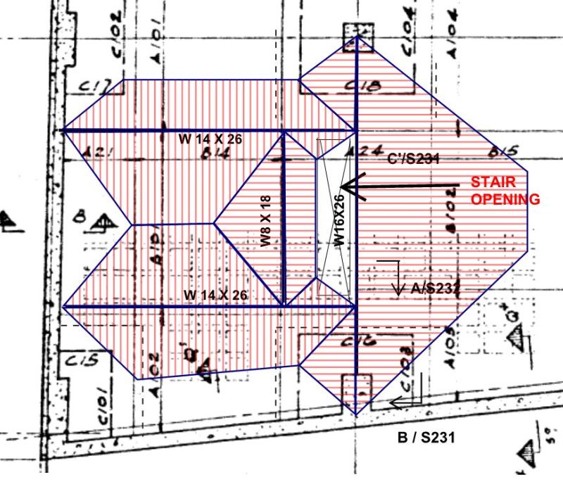
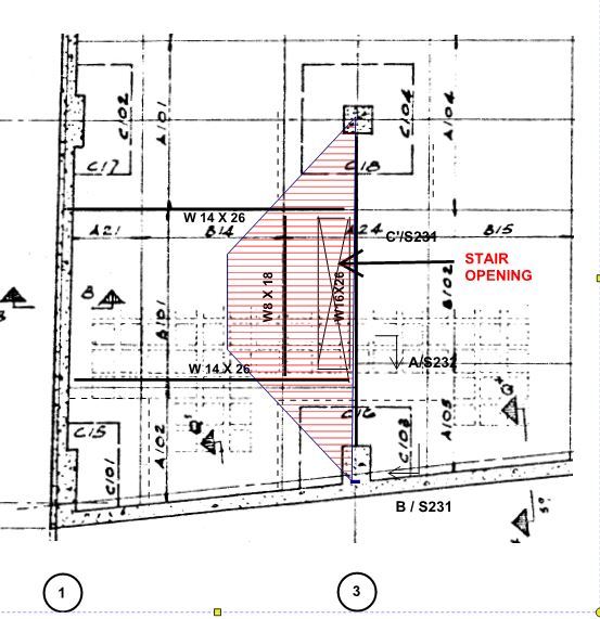
How should the beam loading be determined when checking steel beam framing that was placed some years ago around an area to provide supplementary support where a new stair opening was cut in a two-way slab floor. I don't know that modelling it in SAFE will necessarily give the answer, since it is not apparent what load should be applied to simulate the cutting of the opening. The steel beams were placed and grouted tight to the slab before the opening was cut. The opening removed 1/2 the column strip (bottom bars) in one direction, and all the middle strip (top bars) in the perpendicular direction. The steel beams were grouted tight to the underside of the slab with 2½" thickness of grout.
 
Replies continue below

Recommended for you

Don't just talk abut the configuration.

Please draft the plan, elevation and section views so we know what issues you are facing.

Given some geometry of the floor ans original beams, plus the new ? beams when the hole was cut, the floor loading is determined not by the structure underneath the floor, but by the weight and movement and friction above the floor. (And the floors above the current one).
 
I would expect every structural engineer on this system experienced in building design knows what I am talking about.
 
I think that the sketch shown below would be a reasonable, conservative estimate of the potential loads that your beams may see. The red lines indicate where the tributary loads would head off to, hopefully.

There may be two separate questions to consider here:

1) How much flexural capacity do the beams need to resist the load that the beams could potentially attract were they rigid and to remain so. That's the question that I've tried to answer.

2) How much flexural capacity do the beams need to add to the waffle slab floor system in order to replace the capacity lost when the opening was cut.

The answer to #2 could be a fair bit less than the answer to #1.

Capture_MMM_dvrvh0.jpg


I like to debate structural engineering theory -- a lot. If I challenge you on something, know that I'm doing so because I respect your opinion enough to either change it or adopt it.
 
That is an excellent way of summarizing it and precisely as I had been thinking of it. Your loading diagram is also pretty much as I had used in doing my calculations. But that assumes that the waffle slab structure takes no load (other than to span between the steel beams), which would be ultra conservative. When the steel beams are checked that way, the conclusion is that one of the steel beams would have collapsed long ago, since the main beam (#4) has less than 1/3 of the required capacity when checked by LSD. This is partly because one of the beams was found to be W16x26 (by on-site measurement) rather than the W16x36 shown on the drawings. Since it has not collapsed and gives no indication of doing so, I have to conclude that it is seeing a lot less load. So my question was how to determine how much load that is really going to it.

Because there is a schedule crunch, I issued beam strengthening drawings based on a loading pattern similar to what you showed, but I am still interested in how to determine the load the beam actually takes. Probably not an easy thing to do, because the waffle was already taking the load before the beam was installed.
 
ajk1 said:
but I am still interested in how to determine the load the beam actually takes. Probably not an easy thing to do, because the waffle was already taking the load before the beam was installed.

Right. The difficulty in accurately assessing the loads on the beams is probably why this thread hasn't garnered too many responses so far. Coming up with something that's simple, realistic, and reliably conservative is tricky. Some thoughts:

1) You could use SAP to do a staged analysis. Too much work for me.

2) You did exactly what I would have done. My reasoning would be that most of the cost in this will be labor, not material. As such, if the beams needed reinforcing anyhow, reinforcing them with larger tees probably isn't a real big deal.

3) If I were the original designer, I would have detailed the W14x26's to not be in contact with the waffle slab for just this reason.

4) Wherever a beam has been installed, I would think it reasonable to assume that beam shares load with a few of the neighboring waffle ribs based on stiffness. If I remember correctly, however, your ribs are pretty shallow.

5) One approach would be to allow the beams to fail in bending moment. As long as the resisting moment that they do supply, taken in conjunction with the flexural capacity of the adjacent waffle slab, is adequate for the applied loads, all should be well. You'd want to conservatively design your beam support connections of course. And deflection analysis would be a bear.

It's considerably more aggressive, but I might be able to get behind #5 with the load distribution shown below. I'd argue that the load to the right of the beam can probably still be supported by the 1/2 middle strip that remains and that the waffle slab to the left of the beam is still pretty much going to act like a two way plate.

Capture_qpxp1r.jpg


I like to debate structural engineering theory -- a lot. If I challenge you on something, know that I'm doing so because I respect your opinion enough to either change it or adopt it.
 
ingenuity said:
1/2 column strip?

Yup. My bad.

I like to debate structural engineering theory -- a lot. If I challenge you on something, know that I'm doing so because I respect your opinion enough to either change it or adopt it.
 
The original drawings did show that not all the ribs were to be grouted. The ribs are 5" deep plus 2½" slab = 7½" total. Ribs at 24" centres. I am not so sure that the extent of the ribs that were grouted has that much of an effect on how much load really goes to the steel beam. I would have thought is was more affected by the relative stiffness of the waffle slab (half panel say) versus the steel beam.

I too felt that the waffle slab half column strip could still carry its share of the load after the opening was cut. I was thinking that only the half column strip load capacity was lost. So since the positive moment taken by half the column strip is half of 60%, or 30% of the total panel moment, plus a percentage of the weight of the new masonry walls of the stair enclosure, that might be all that the beam has to take. The moment in the beam came to the following in each of the cases we calculated:

415 kN.m for Case 1: all of the ribs grouted to the steel beam
310 kN.m for Case 2: only some of the ribs grouted tight
226 kN.m for Case 3: 30% of the panel load

202 kN.m for Mr of W16x26 (fy=303 MPa) if laterally supported.

In each case the new beam would also take some of load of the new block wall; we took 100% of the weight of the new block wall onto the steel beam in our check.
 
ajk1 said:
I am not so sure that the extent of the ribs that were grouted has that much of an effect on how much load really goes to the steel beam.

If there's a physical gap between the beam and the waffle slab ribs, then no load would go to the beams. That's the point that I was trying to make and what I would have done for the W14x26's at least. My money says that those beam exist only to hold up the W8. I doubt the original designer ever intended them to mess with the general slab-ish behavior of all the stuff to the left of the new shaft.

Putting 100% of the masonry on the beam makes sense to me.


I like to debate structural engineering theory -- a lot. If I challenge you on something, know that I'm doing so because I respect your opinion enough to either change it or adopt it.
 
ok, I understand the point. Thanks.
 
Status
Not open for further replies.

Part and Inventory Search

Sponsor