Continue to Site

Eng-Tips is the largest engineering community on the Internet

Intelligent Work Forums for Engineering Professionals

  • Congratulations cowski on being selected by the Eng-Tips community for having the most helpful posts in the forums last week. Way to Go!

Aluminium RHS bolted moment connection

Status
Not open for further replies.

Euler07

Structural
May 7, 2023
78
Hi everyone,

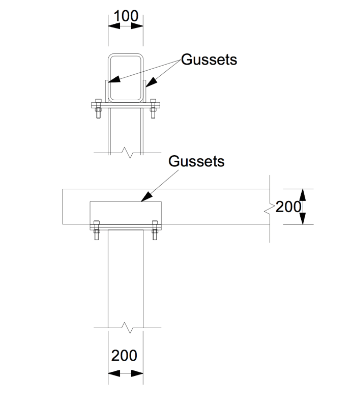
I have a cantilevered aluminium structure that needs a bolted moment connection between the column and rafter (see the image). The cantilever length is approx. 3m and the wall of the RHS is between 6mm to 9mm depending on the final design.

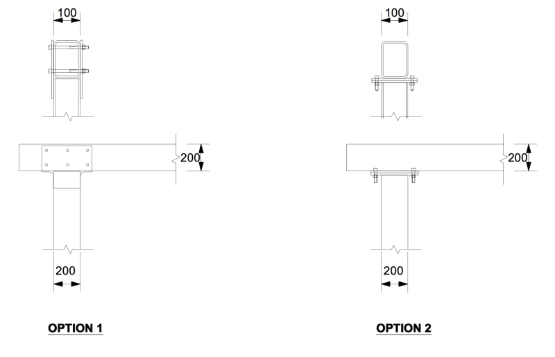
I was originally going with option 1, however the builder said the wall of the aluminium RHS sometimes deforms when tightening the bolts and asked if we need “crush tubes” (tubes inside the RHS that will prevent crushing of the RHS wall). I have searched for information on crush tubes in aluminium but can’t find anything. Does anyone have experience on this type of connection and was crushing of the wall an issue?

Otherwise, I was considering using option 2. However, the client doesn’t want gussets (they want a ‘clean’ look), therefore I would prefer option 1 where I can adjust the weld length on the column and bolt spacing on the rafter as required.

Any thoughts?
Untitled_2_jot7lp.png
 
Replies continue below

Recommended for you

Bolted moment connections with hollow section is a tougher task than it may at first seem! If you want high strength and stiffness then things start getting quite complicated quite quickly. Alternatively if you oversize you members you can make the connection design simpler. I've been looking quite closely at both these types of connection as well as a couple others. Though I've been doing steel not alumninium.

Crush tubes are simply pipe bolted between the two holes on the inside of the hollow section being clamped. Without them or something similar you are unlikely to be able to achieve full bolt tension without crushing the hollow section.

Also note that Option 1 is effectively pinned connection unless you ensure that the friction between the faces is sufficient to ensure a non slip condition.

For what it is worth. For my design I'm likely going with gusseted Option 2 style connection for major members. Likewise the my client may not be excited by my gusseted connection. Hence I'm restrict it to only a few locations

For more minor members that I want moment connections I'll go with option 1 with crush tubes and a significant number of bolts to achiever suitable friction. I'll probably end up with more pinned connections than originally planned due to the difficulty and cost of achieving a suitable connection.


I found the IdeaStatica software an excellent tool. I used the trial version to test out and iterate some approaches. Much faster than hand calcs.
 
I'm assuming you wanted bolted due to field welding concerns. Unless you are re-tempering the plates after welding, I doubt the bolts will control as the weld affected zone will be very low capacity for aluminum. What the contractor is asking for is either a tube insert, or a pipe sleeve that keeps the bolt from crushing, depending on your wall thickness, I could see you needing this as I assume you are looking at a slip critical connection. Out of curiosity, could you achieve option 1 using screws in lieu of thru-bolts?
 
Hey guys thanks for the thoughts.

human909 said:
Also note that Option 1 is effectively pinned connection unless you ensure that the friction between the faces is sufficient to ensure a non slip condition.
Mmm, I guess I assumed that the bolt bearing onto the aluminium wall would be sufficient. Is this incorrect? I calculated the bolt bearing force for the applied moment vs the bearing capacity of the aluminium wall. If this is indeed a connection that could slip then I would be more inclined to go with option 2. Do you think the image below would be suitable for the gussets? (i.e. a reverse gusset on the top where I could get adequate bolt spacing to satisfy the moment while still preventing moment failure of the plate).

Aesur said:
Out of curiosity, could you achieve option 1 using screws in lieu of thru-bolts?
I don't think this would be an option based on the project, but I would also be personally hesitant to make a critical moment connection screwed for aluminium.

Aesur said:
I'm assuming you wanted bolted due to field welding concerns. Unless you are re-tempering the plates after welding, I doubt the bolts will control as the weld affected zone will be very low capacity for aluminum.
Yes, it needs to be bolted together on site. I initially thought it would be a HAZ strength dominated design but it turns out it is deflection dominated (due to the cantilever). The reduced strength from the HAZ seems to be ok.

3_ks8hkz.png
 
Euler07 said:
Mmm, I guess I assumed that the bolt bearing onto the aluminium wall would be sufficient. Is this incorrect?
It is sufficiently strong. But it is not sufficiently stiff to qualify as a moment connection. You have significant rotation before bearing even begins and even after bearing begins you still have a very flexible connection under load as bolts in bearing is not a stiff connection.

Euler07 said:
2. Do you think the image below would be suitable for the gussets? (i.e. a reverse gusset on the top where I could get adequate bolt spacing to satisfy the moment while still preventing moment failure of the plate).
That could be suitable. But you'd likely need thick lower plate for stiffness and some hefty welds if you have moderate to high moments.
 
Thanks @humam909. I'll go with the option 2 with thick plates in order to get a proper moment connection as you describe.
 
Status
Not open for further replies.

Part and Inventory Search

Sponsor