Continue to Site

Eng-Tips is the largest engineering community on the Internet

Intelligent Work Forums for Engineering Professionals

  • Congratulations cowski on being selected by the Eng-Tips community for having the most helpful posts in the forums last week. Way to Go!

Aligment 1

Status
Not open for further replies.

nry67

Industrial
May 30, 2011
33
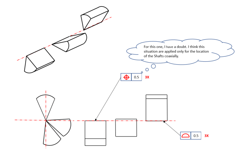
Let's assume that we have 3 same parts (pie form) should be placed on upper level with each vertex of angles on the same axis but not at the same depth.
Can you help me to show the better way to define that on a drawing.
I do 2 exemple, perhaps you have a better than me. Of course I've voluntary abstract the rule of implied.
ALIGMENT_osramj.png
 
Replies continue below

Recommended for you

Will these pieces of pie be produced with a knife-edge?
If they are machined, there will most likely be a small edge-break, so what will you be aligning?
 
These pieces of pie will be produce with a knife-edge
 
So if I understand correctly, you want to apply a control directly on the knife-edges, so that the 3 of them are fitted into a single tolerance zone for alignment. Is that right?
You specified a tolerance value of 0.5, but what do you want the shape of the tolerance zone to be? A cylinder of ⌀0.5?
 
All of the problem is here.
If I consider the tolerance zone let a cylinder, it will be neccessar to use the option with the symbol of POSITION.
But as I explain on my picture, this solution is used only for the coaxiality between a shafts.
It's true? isn't it.
Or, is it possible to place a diameter symbole in the cell of the tolerance value with une information of profil of surface. Knowing that of knife-edge is not a surface but an edge.
Or exist it different something as a alone NOTE for exemple to explain "3 EDGES SHOULD BE ALIGN +/- 0.25"
Or using a profil of line with a note "3 EDGES TOGETHER"
 
I think the note option will be your best bet, but I'm not sure "+/-0.25" is clear. If it means an offset of 0+/-0.25, can the maximum offset between any two edges be 0.25 or 0.5? And since in reality they will not be exactly parallel, how will the offset be determined? Will one of them be used as a reference for the other two and set the measurement direction? If yes, which one will be the reference?

You could write in the note that they are limited as a group in a cylindrical tolerance zone.

The profile of a line idea is interesting. I would like to see opinions about it, whether such use of profile of a line would be interpretable per the standards of dimensioning and tolerancing. The problems with interpretation that I predict are these: since the tolerance zone of profile of a line for a straight element is two parallel lines, what will set the orientation of that two parallel lines? And can that 2D strip tolerance zone include the 3 actual edges? Probably not.
 
Status
Not open for further replies.

Part and Inventory Search

Sponsor