Continue to Site

Eng-Tips is the largest engineering community on the Internet

Intelligent Work Forums for Engineering Professionals

  • Congratulations waross on being selected by the Eng-Tips community for having the most helpful posts in the forums last week. Way to Go!

A quite simple question about reactions in bolted joint

Status
Not open for further replies.

eli28

Aerospace
Oct 20, 2019
109
hello everybody,

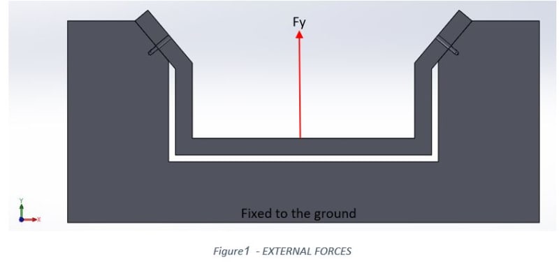
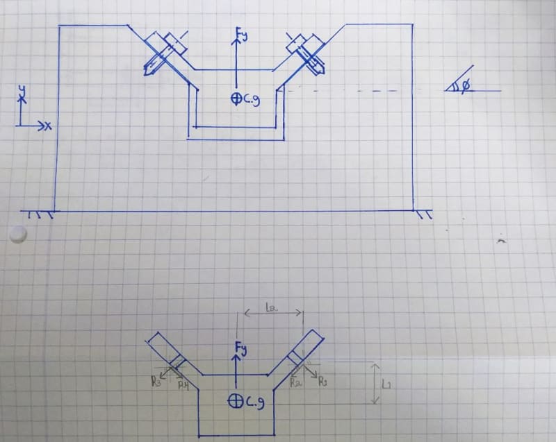
I graduated long ago, and I am trying to figure out how to calculate reactions in bolted joint, so I will be able to know what is the external tensile load on each bolt and in addition the shear force that is actually the outcome of a friction generated by the pressure the bolt exerts.
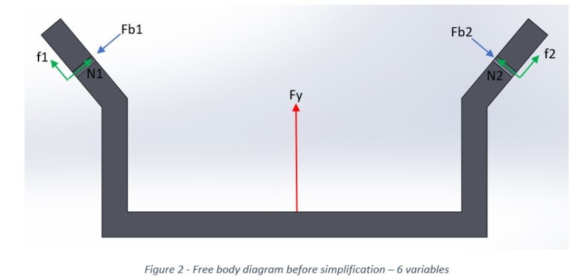
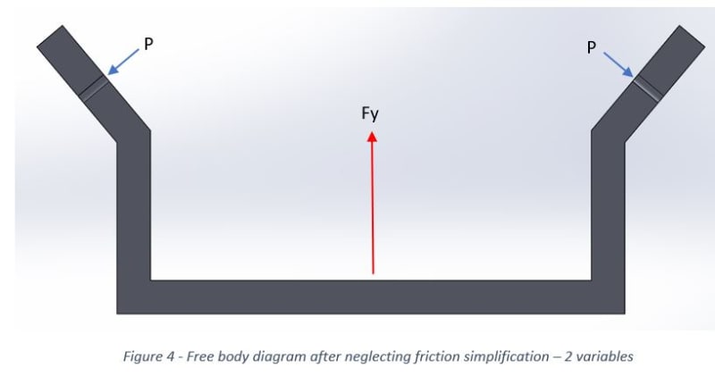
I am trying to draw a free body diagram of a quite simple problem, but I find it difficult to solve since there are only 3 equations and 4 unknowns.
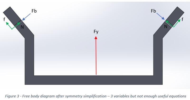
when I try to assume that as a result of symmetry the right reactions = left reactions I get a contradiction while formulating the equilibrium equation in the X direction.
%D7%9C%D7%9B%D7%99%D7%93%D7%94_aybrrm.jpg
 
Replies continue below

Recommended for you

Don't forget your friction equations:

R4 = mu * R3,
R2 = mu * R3
 
Hi eli28

How are the external loads applied and where on the diagrams? Also include the magnitude of the the external loads.
When the bolts are tightened up the friction generated between the two clamped faces will depend mainly on the bolt preload and the surface finish between clamped parts as well as a coefficient of sliding friction.


“Do not worry about your problems with mathematics, I assure you mine are far greater.” Albert Einstein
 
How rigid are the flanges? If (just for a moment) you imagine their connection to the central component to be pinned joints, does that affect your view of the problem (or is it a more academic exercise than that)?

A.
 
Sum forces y: Fy - 2R3y = 0
Sum forces x: R3x - R3x = 0
R3x = R3sin(theta)
R3y = R3cos(theta)

There are no external forces parallel to faying surfaces for friction to react to.

Ted
 
hello everyone and thank you for replying.
I am going to answer each one of you in this post.

BrianE22
I initially thought exactly like you - that I have to automatically write down the friction as mu*R1.
But I am not sure this is true since this expression (mu*R1) is the maximum static friction that can be supplied and not necessarily the existing one.

There might be 2 cases (I am interested in checking the 2nd one):
1. there is a much more lower friction than mu*R1.
I attached a file from a mechanical engineering book with a solution to a different problem, and there you can see that they don't take the friction (Fc2y) to be automatically equal to mu*Fc2x.
In addition, when you take their answers and divide them (Fc2y/Fc2x) you get a small fraction (0.03) that is probably not the friction coefficient.
2. there is a need in much more higher force than mu*R1 for achieving an equilibrium.
In such case the bolt preload is insufficient for making enough friction and we should add pins.

what do you think? is it right?
Thanks!
 
 https://files.engineering.com/getfile.aspx?folder=76e5931c-6331-4d61-bf29-5e7611beecb9&file=FBD_EXAMPLE_WITH_A_BOLTED_JOINT.pdf
desertfox
The external load is indicated in the sketch as Fy, and it's a force that pass through the symmetry plane and c.g.
I need a solution that uses parameters, and that's the reason I didn't add a value.
Please see the answer I gave to BrianE22 regarding the friction force.
I will be happy to hear what you think about it.
 
zeusfaber
Good question.
In this stage I try to solve it as an academic problem in which the flanges are infinitely rigid and that's why there are no more reactions. My aim now is finding out roughly which and how many bolts I need. When I proceed with the design I will use FEA to analyze it more realistically and I will use the handwritten calculation as a means for checking that I have no mistake with my FEA.
 
hydtools
I would be comfortably agree with this statement ("There are no external forces parallel to faying surfaces for friction to react to") if the external force would be perpendicular to the surfaces that can develop friction...this is not the case [smile2]
 
Your joint configure is complex and statically indeterminate. The following are the loads coming into play (depending on angle and coefficient of friction)
1. Bolt and member preload.
2. Bending moment on member due to offset force
3. Component of external force along axis of bolt.
4. Normal force on member/bolt interface due to preload and component of external force perpendicular to bolt.
5. Frictional force along bolt-member interface due to normal load in 4. above.
6. Shear force on bolt section depending on frictional force developed at interface.

As the loading becomes statically indeterminate the displacement compatibility will come into play.
As there is no simple formula in Theory of Elasticity, a FEA solution can be the only way out.

Engineers, think what we have done to the environment !
 
Hi eli28

Yes your problem is statically indeterminate, however you could get some idea of the axial loads in the bolts by drawing a triangle of forces diagram using Fy as the vertical force and draw the lines of action acting at ninety degrees to the angled faces and close the triangle, if the bolts are symmetrical about the C of G where the load acts then the reaction in each bolt would be equal in theory. Once I knew what the load was from the triangular forces diagram I would size the bolts with a good margin of safety, my solution isn’t perfect but it’s a starter for ten👍😀

“Do not worry about your problems with mathematics, I assure you mine are far greater.” Albert Einstein
 
there's no applied Fx, the load/reaction system is symmetrical. So the two reactions, the two vectors at the two fasteners are mirror images.

what this means is that R1 = R3 and R2 = R4 (since they've been drawn sensibly mirror images).

the free body diagram is a triangle, an isosceles triangle, with the two faster reactions being vector summed to the applied (vertical) load.

what this means is R2 and R4 are not zero, but equal.

yes the problem is redundant, but we can makes some conservative guesses about friction to solve it without complication. mu = 0.1, 0.3, 0.5, 1?
as desertfox said, design it with a large MS. I suggest the actual mode of failure would be the failure of the heads, being pried off, which is a whole different thing !

another day in paradise, or is paradise one day closer ?
 
The friction force in the example was determined to be equal to the tongue weight. There was no calculation made to equate friction force capacity and preload. It was not determined if friction force capacity was < or > than the force of the tongue weight. Would the joint slip or not?

Is there a weight associated with the cg in the OP problem?

Ted
 
the relationship of the example (05:36) to the OP is tenuous at best. One problem is symmetric, the other not (this changes things enormously).

As drawn the OP is a relatively simple problem.

The simplest solution is to say each bolt reacts Fy/2 and calculate tension and shear from components. Friction (from an up force, separating the fitting from the base) is likely to be negligible. What does confuse the solution is ... is there prying load (from the tips of the fitting, bearing down on the base) ?

another day in paradise, or is paradise one day closer ?
 
If the attached shape/bracket lifs off the surface, the capscrews will see both tension and bending.

Ted
 
Hello everyone and thank you for participating in the discussion.
I would like to sum up with all the answers I got and after consulting with my former statics lecturer.
you are invited to say if you agree or not.

Here we can see the original problem with the single external force exerted on it.
1_kg5dt0.jpg

Here is the most detailed Free Body Diagram before starting to simplify and omit variables.
2_vbkkgg.jpg

First quite simple and intuitive simplification is assuming symmetry, so all the reactions on the right side are equal to the left reactions. Now we are left with 3 variables, but when applying 3 equilibrium equations we find out that one of them is useless (we get 0=0).
3_idbz87.jpg

The second assumption that we are forced to take is that the friction is quite negligible as some of you already wisely suggested. Now we can say that we have resultant force that we call p=Fb-N, and now we can solve the problem. After we find P we can find out its 2 components N (the axial compression force of the clamped members) and Fb (the axial tension force of the bolt) from calculating their relative rigidity as described in any design book in the chapter that deals with bolted joint.
4_falbtu.jpg


As some of you said, life is more complicated and in a problem that isn't infinitely rigid there will be additional forces.
In addition the bolt's head will be be subjectrd to bending.

For me it was very confusing - finding out that after 4 years in academy a quite simple problem is found out to be unsolvable unless you neglect some components. What did old fashin engineer do when they calculated complicated things such as planes, bridges etc. ?!
 
It lead to what is now referred to as "over-engineered".

Ted
 
1) the problem is not unsolvable ... if you can define the friction (if you want to account for it)

2) why neglect the simplest reaction ... Fy/2 vertical at both fasteners ?

3) Figure 3 has two unknowns (N and F) because you've applied symmetry. But because you've applied symmetry you can't determine from statics these reactions. But you can solve the problem with other analysis tools.

another day in paradise, or is paradise one day closer ?
 
You will have non-zero moment reactions at the bolted connections. I don't see those on your FBD.
 
Hi eli28

Glad you got it sorted and yes I agree with your figure 4 diagram, which is what alluding to in my post👍

“Do not worry about your problems with mathematics, I assure you mine are far greater.” Albert Einstein
 
Status
Not open for further replies.

Part and Inventory Search

Sponsor