wroggent
Electrical
- Aug 20, 2012
- 288
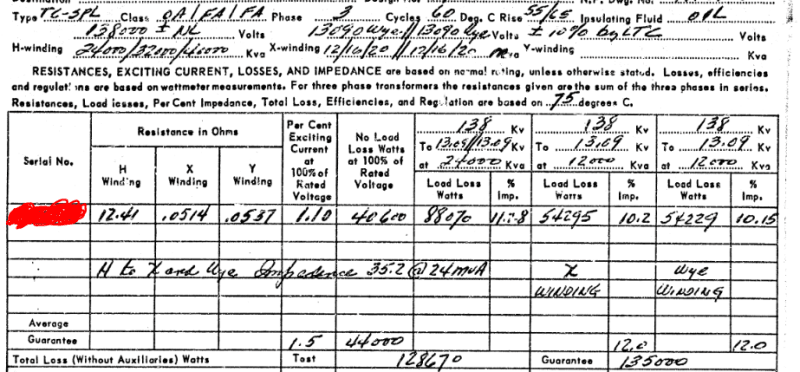
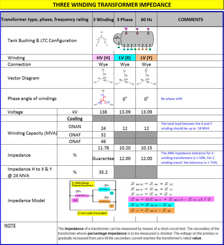
I don't know much about three winding transformers and I need some help figuring out what impedance value I should use. A look at our data base says that the impedance of the transformer is 11.28% (I'd expect two values, one for each low side winding, but there is not). Below is a snip from the test report for the transformer, you will find 11.28% given as the impedance for "138kV to 13.09/13.09". I'm not sure what that means or if it is the correct value to use.
There are four impedance values that appear on this report and I'm not sure what they all are. There's 11.28 @ 24MVA, 10.2 @ 12MVA, 10.15 @ 12MVA and 35.2 at 24MVA.
Defining
Z12= impedance measured from winding 1, with 2 shorted and 3 open
Z13 = impedance measured from winding 1, with 3 shorted and 2 open
Z23 = impedance measured from winding 2, with 3 shorted and 1 open
and
Z1, Z2, and Z3 are the series impedances for the windings
where
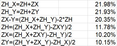
Z12 = Z1 + Z2
Z13 = Z1 + Z3
Z23 = Z2 + Z3
and
Z1 = 1/2*(Z12+Z13-Z23)
Z2 = 1/2*(Z12+Z23-Z13)
Z3 = 1/2*(Z13+Z23-Z12)
Arbitrarily assigning 10.2 and 10.15 to either of the low voltage windings I'm guessing that:
Z12=10.2
Z13=10.5
Z23=17.6 (35.2*12MVA/24MVA)
So
Z1 = 1.375
Z2 = 8.825
Z3 = 8.775
And I'm guessing 11.28% is supposed to be (Z1 + Z2//Z3)*24MVA/12MVA? Or (1.375 + 8.825*8.775/(8.825+8.775))*2 = 11.56%
But I really have no idea. I am trying to find an impedance value I can lump with the upstream 138kV network impedance to serve as my source model.
There are four impedance values that appear on this report and I'm not sure what they all are. There's 11.28 @ 24MVA, 10.2 @ 12MVA, 10.15 @ 12MVA and 35.2 at 24MVA.
Defining
Z12= impedance measured from winding 1, with 2 shorted and 3 open
Z13 = impedance measured from winding 1, with 3 shorted and 2 open
Z23 = impedance measured from winding 2, with 3 shorted and 1 open
and
Z1, Z2, and Z3 are the series impedances for the windings
where
Z12 = Z1 + Z2
Z13 = Z1 + Z3
Z23 = Z2 + Z3
and
Z1 = 1/2*(Z12+Z13-Z23)
Z2 = 1/2*(Z12+Z23-Z13)
Z3 = 1/2*(Z13+Z23-Z12)
Arbitrarily assigning 10.2 and 10.15 to either of the low voltage windings I'm guessing that:
Z12=10.2
Z13=10.5
Z23=17.6 (35.2*12MVA/24MVA)
So
Z1 = 1.375
Z2 = 8.825
Z3 = 8.775
And I'm guessing 11.28% is supposed to be (Z1 + Z2//Z3)*24MVA/12MVA? Or (1.375 + 8.825*8.775/(8.825+8.775))*2 = 11.56%
But I really have no idea. I am trying to find an impedance value I can lump with the upstream 138kV network impedance to serve as my source model.
![[bigsmile]](/data/assets/smilies/bigsmile.gif "[bigsmile] [bigsmile]")