Continue to Site

Eng-Tips is the largest engineering community on the Internet

Intelligent Work Forums for Engineering Professionals

  • Congratulations waross on being selected by the Eng-Tips community for having the most helpful posts in the forums last week. Way to Go!

120VAC/60hz small electric motor overheating on lower supply voltage.. some type works OK .....

Status
Not open for further replies.

jpdesroc

Electrical
Nov 29, 2019
7
Hi,
I'm a newbie in the small electric motor hacking world.
I need info about how to drive a standard 120vac motor
with a variable AC source without overheating the motor
at low speed...

Here is my project:
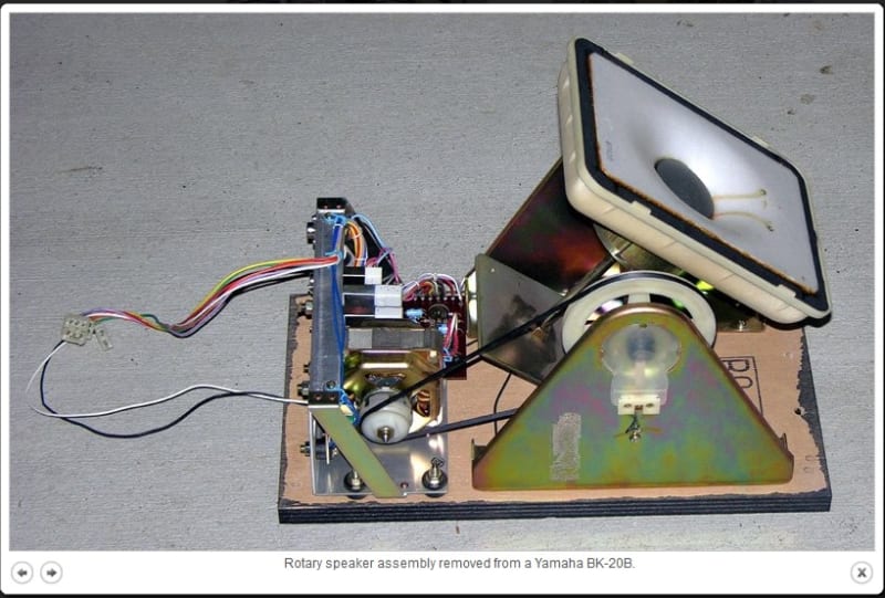
Yamaha organ instrument used to include, in some of their organ,
what they called a rotary speaker unit which is in fact
a rotating speaker driven by a pulley and an 120VAC-60hz electric motor
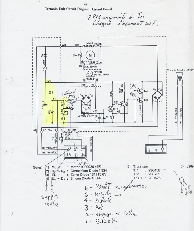
driven by a variable speed circuit. (the 120VAC is lowered for slower speed)

Here attached are pictures of the unit, The motor driver circuit and
because I just have all the needed material to build
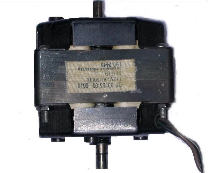
a clone of this unit BUT the special Yamaha AC motor,
I use a substitute motor for my project..

My problem is that my substitute motor which is the exact size/power
of the Yamaha is overheating when the VAC driving it is lowered.
I had to put a small fan over it to keep it from getting too hot !!

I suspect there is some windings in the Yamaha motor
that keeps the motor from overheating and accept
a lower AC than 120VAC..
Probably a current phase between stator and rotor
that gets 'upset' at slower speed than expected for 60hz use.. (??)

Can you tell what are the differences between both motors
and what type should I buy (and where) ??

Many Thanks !
Jean-Pierre Desrochers
Canada

Yamaha_rotary_speaker_unit_dedehb.jpg
Motor__driver_circuit_rwgasg.jpg
Substitute_120VAC_60hz_motor_p07owq.jpg
 
Replies continue below

Recommended for you

Go to a thrift shop or a Value Village and look for a cheap, variable speed, pedestal fan.
Don't spend more than you can afford to lose if it doesn't work.
I'm guessing that the Yamaha motor is 3500 RPM.
The fan motor may be 1600 RPM or 1700 RPM.
You may have to change pulley ratios to get top speed. (If you need top speed.)

Bill
--------------------
"Why not the best?"
Jimmy Carter
 
I thought these type of variable speed fan had like 3 fixed speeds.. (??)
If I use the maximum speed tap (3 speed taps inside these motor I think)
and drive it with my variable AC supply current circuit (the circuit shown in previous post)
you think it will vary its speed without overheating at very low speed ?
If it is so, why ??
What are the BIG differences between my substitute motor
and these pedestal fans ?
Thanks for your help !
 
That is a special motor.
The "sub" winding appears to be a starting winding.
I don't see a starting winding in the picture that you posted.
What you cannot see is the squirrel cage winding on the rotor.
The squirrel cage winding on the rotor of the Yamaha motor will be designed for low speed torque rather than for efficiency.
From basic motor theory, the starting winding provides an offset magnetic field to start the motor turning and to determine the direction of rotation.
A shaded pole motor uses two shorted copper links for that purpose.
Given a constant torque load on a motor, the lower the applied voltage, the more Amps it takes to develop the same HP.
So, as you reduce the voltage, available HP goes down and heat goes up.
With the load characteristics of a fan, this is not a problem.
Tapping the motor windings is only one of several ways to slow down a pedestal fan.
Solutions:
Try a bigger motor.
Try a different pulley ratio so you don't have to drop the speed as much.
Use a universal motor. (A motor with brushes.)
An old vacuum cleaner may have a suitable motor.

Bill
--------------------
"Why not the best?"
Jimmy Carter
 
Now I understand..
So using the maximum speed tap of a standard table fan (with sufficent motor torque)
and drive it with my variable AC supply current circuit (the circuit shown in previous post)
the overheating will not occur at very low speed ? OK.

By the way, I cannot use a motor with brushes because of the noise
generated !!! It is a musical instrument and must be quiet...
 
You are going to have to try and see.
There is not enough information available to say for sure.

Bill
--------------------
"Why not the best?"
Jimmy Carter
 
Bill,
What I meant was :
A table fan has a different induction motor type as the one I used as a substitute ?
If so, YES I'll give it a try !
 
The diagram of the motor itself looks to be a PSC (Permanent Split capacitor), but I'm not clear on why one side of the circuit for it is going through a full wave diode bridge rectifier. Interesting...


" We are all here on earth to help others; what on earth the others are here for I don't know." -- W. H. Auden
 
I was confused by the diagram and the picture. I think that the picture may be the replacement shaded pole motor that gets hot.
I think that they are using T13 and T14 to control the current to the motor.
That does look like a diagram for a PSC motor.
I suspect that it has a special, high resistance rotor to give it something like design "D" characteristics.
Bill
--------------------
"Why not the best?"
Jimmy Carter
 
>The diagram of the motor itself looks to be a PSC (Permanent Split capacitor),
>but I'm not clear on why one side of the circuit for it is going through a full wave diode bridge rectifier. Interesting...

The full wave bridge rectifier is to only keep the positive side of the 60hz waveform
to both TR3-TR4 and use them as a variable power resistor in series with the motor.

But what interest me in the last posts is the mention of PSC motor (Permanent Split capacitor).
Are they more tolerant from droping the AC voltage to them
to vary speed ?
Do you have a picture of such a motor (in the size of what I'm looking for which draw around 0.6amp 1800RPM) ?

 
What speed range does the original motor operate over?
There is not too much difference in motor stators.
Basically a winding induces an alternating magnetic field in the stator.
The difference is in the rotor.
A typical rotor is composed of a stack laminations with holes punched through the stack.
While larger motors may use copper bars to form the squirrel cage winding it is common to cast the squirrel cage winding on small motors.
An aluminum alloy may be used to cast the rotor or squirrel cage winding.
Here is where it gets interesting.
The slower the rotor turns the higher the frequency of the current through the squirrel cage winding.
The area of the squirrel cage bars affects the characteristics.
The depth of the bars below the rotor surface affects the characteristics.
Some motors use a double squirrel cage; A set of bars near the surface and a second set of bars deeper in the rotor.
The deeper bars become more effective as the speed increases and the rotor frequency drops.
Some double squirrel cage designs use a figure 8 shape with the upper bars connected to the lower bars through a narrow bridge.
We study the effects of different designs of squirrel cage windings to gain an understanding of induction motor characteristics, and then almost never refer to the designs directly.
When we are selecting a motor for an unusual application, we look for a motor with suitable characteristics.
We select the motor based on the speed torque curve.
We know that the curve is greatly affected by the design of the squirrel cage winding but we almost never know the details of the actual squirrel cage winding in our chosen motor.
The original Yamaha motor has been designed to work outside of the normal operating envelope of an induction motor.
We can only guess as to the specific design and offer suggestions for a work-around.
Me said:
There is not too much difference in motor stators.
One exception that may be applicable.
The current through a stator winding is limited mostly by the inductive reactance of the motor. (This will drop as the rotor increases in speed.)
In a small motor an intentionally high resistance winding may be used to further limit the current at low speeds.


Bill
--------------------
"Why not the best?"
Jimmy Carter
 
Thank you Bill for such a detailed explaination !
What a treat !

Here are more explanation of what I measured and what I'm about to experiment:

The original Yamaha motor is a 1800RPM (in fact 1714RPM measured) at full speed
and drops to 200RPM at slow speed. If you divide 1714 by 200 you get 8.57.
If I keep the fact that an induction motor speed is relative to the AC frequency
it's powered with I should divide the AC60hz by 8.57 which gives 7Hz.
An inverter circuit that drives 120VAC@7Hz to my motor is to be tried...
I found the following simple circuit:

The 4047B IC would be replaced by crystal oscillator (MC14060)
with a standard 3.5797Mhz crystal divided by 524288 (2^19)
which gives 6,827Hz. this final clock would go through
2 phase inverters to get 2 clock 180 degrees opposed
to drive the power transistors to a stepup transformer
that step up everything at 120VAC.

One thing I don't know so far is what will be the motor behaviour
at such a low frequency.. The phasing between the windings..
 
You are neglecting the Volts per Hertz ratio.
There are two limits on the maximum voltage that be applied to a motor.
One limit is the insulation value. This is generally not a concern.
The other limit is magnetic saturation.
Once the strength of the magnetic field saturates the iron the impedance of an inductor drops drastically.
If too high a voltage saturates a motor field, burnout may occur in seconds.
The principle component of the impedance is inductive reactance and is frequency dependent.
What does this mean in simple words?
If you drop the frequency, the motor iron may saturate and burnout may be seconds away.

Fortunately the relationship is quite linear.
120 Volts and 60 Hz is a V/H ratio of 2 Volts per Hertz.
At 7 Hz you should not apply more than 14 Volts.
Drop your voltage in the same ratio as you drop your frequency.
That may save some smoke stains on the ceiling. grin


Bill
--------------------
"Why not the best?"
Jimmy Carter
 
So 14VAC@7Hz will give enough power to the motor to spin ?
I will give it a try this afternoon !
I'll rise VERY slowly the AC voltage and keep an eye
on the motor behaviour.
I never heard about this V/H ratio at all..
Thank you very much !
 
I would start with 14 Volts or raise the voltage quickly.
There is a reason but my fingers are tired.
The motor won't be cooling itself at 200 RPM.
You may have to use a fan.
Your inverter will have to supply enough current for the starting surge.
Based industrial induction motor characteristics the running torque should be good.
Spinning the speaker fast will churn a lot of air.
At 200 RPM versus 1700 RPM the torque required should be much less.


Bill
--------------------
"Why not the best?"
Jimmy Carter
 
Status
Not open for further replies.

Part and Inventory Search

Sponsor