Are you familiar wit the basic three wire motor control circuit?
Start with a basic three wire motor control circuit.
Add low level contacts in series with the stop button.
Add high level contacts in series with the start button.
If the level signals must come from the DCS, functionally the DCS contacts may be used directly or you may use an interposing relay(s).
Caveats;
1. You may wish to avoid short stopping.
If the current to a running motor is interrupted for a short time and then re-energized, there may be violent transients developed, both electrical and mechanical.
The electrical transient may exceed locked rotor current. The mechanical transient may break motor shafts or damage driven equipment or break couplings.
The danger zone is generally less than 8 seconds and is the worst in the first second or less.
The danger time is when the upper limit has closed but the liquid level has not dropped enough to open the high level contacts.
This may be avoided by interposing a timing relay.
Would you like to humour me as I revisit a distant past?
Many years ago I taught motor control circuits to classes of journeymen electricians.
We had actual motor control equipment and small motors so that the students could wire up their circuits and prove them out.
The students started by wiring up each typical control scheme for a single motor.
They were supplied with a booklet of wiring diagrams.
Once they completed the single motor assignments they started working on multiple motor control schemes.
For this part of the course, no diagrams were supplied.
The students were given a description of the intended operation and the students developed their own diagrams.
I did not give instructions but did ask leading questions.
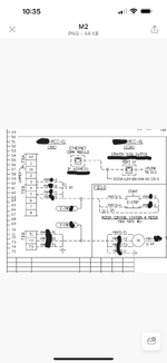
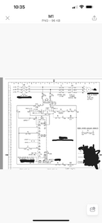
See if you can download the diagram and then edit it.
You start by making additions and posting them.