Continue to Site

Eng-Tips is the largest engineering community on the Internet

Intelligent Work Forums for Engineering Professionals

  • Congratulations Ron247 on being selected by the Eng-Tips community for having the most helpful posts in the forums last week. Way to Go!

L-G Fault Zero Sequence Current in un-faulted phases

rockman7892

Electrical
Apr 7, 2008
1,178
I know that for a single L-G fault the ground fault current If on the faulted phase is represented as 3I0 and it is this 3I0 that can be measured and represented as ground fault current. I also understand that this 3I0 value comes from the contribution of both the pos sequence, neg sequence and zero sequence current on the faulted phase (I1=I2=I0=1/3IF).

What I am not clear on however is what if any zero sequence is present in the other two unfaulted phases during a L-G fault. I recall reading somewhere once that there is I0 current in the other two phases however they are offset by the negative sequence current in those phases?

If there is I0 current present in the other un-faulted phases can it be measured with CT/relaying on that phase or is it offset to the degree where it is not measurable?

Appreciate any insight in helping my understanding.
 
Replies continue below

Recommended for you

The zero sequence current in each phase is identical to the zero sequence current in the other two phases. The positive sequence current in each phase has the same magnitude as that in each of the other two phases with an angular difference such that A leads B leads C by 120 degrees each. Likewise, the negative sequence current in each phase has the same magnitude as that in each of the other two phases with an angular difference such that A leads C leads B by 120 degrees each.

In many fault cases, for a single phase fault, the positive, negative, and zero sequence currents of the faulted phase are in phase with each other and of equal magnitude. I1 + I2 + I0 = 3I0. The angular differences between the three sequence keep them from adding up like that in the other two phases. But look at the current into/out of a grounding bank for a fault elsewhere on the system. Just I0 in each phase, all on top of each other. But the three add to 3I0.

But you can only calculate the sequence currents; all three phase magnitudes and angles need to be known. But then, by definition, you can calculate each, and also by definition, the magnitude of any sequence in each phase will be the same as the other phases, though the magnitudes of the three sequences can be vastly different.
 
I think the answer is yes, the other two phases technically have I0 current, but you can’t measure it as it’s canceled by the positive and negative sequence currents in the phases without the fault, so the current is zero in the unfaulted phases.
The only exception is that you can absolutely measure the I0 current if you have a separate grounding bank on the system, then you will see a perfect representation of I0 current. (currents exactly in phase on all three phases)
 
If we follow, for instance, IEC 60909-0 the short-circuit current is:
4.2 Initial symmetrical short-circuit current I”k
I"k=sqrt(3)*c*Un/(Z1+Z2+Zo)
For a far-from-generator short circuit , the absolute value is calculated by:
I"k=sqrt(3)*c*Un/(2*Z1+Zo)
That means if the short-circuit is phase A to Ground, actually only phase A presents the current, and B and C a very small residual load current only.
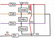
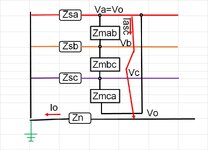
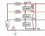
If Zs it is the self-impedance of the phases and Zm is the mutual impedance
Va=Zs*Ia+Zmab*Ib+Zmac*Ic+Zn*Io
Vb=Zs*Ib+Zmab*Ia+Zmbc*Ic+Zn*Io
Vc=Zs*Ic+Zmac*Ia+Zmbc*Ib+Zn*Io
If Ia≈Iasc and Ib=Ic≈0 then
Va=Zs*Iasc+Zn*Iasc=(Zs+Zn)*Iasc
Vb≈Zmab*Ia+Zn*Io
Vc≈Zmac*Ia+Zn*Io
Let's take Ia1, Ib1,Ic1 three imaginary phasors as positive phase sequence
Ia1≈Ia/3;Ib1=Ia1*α^2;Ic1=Ia1*α where
α=-1/2+j1/2*sqrt(3) [in complex]
Ia1+Ib1+Ic1=0
The same Ia2, Ib2,Ic2 three imaginary phasors as a negative phase sequence
Ia2≈Ia/3;Ib2=Ia2*α;Ic2=Ia2*α^2
Then, Iao, Ibo,Ico are three imaginary phasors as zero phase sequence where Iao=Ibo=Ico=(Ia+Ib+Ic)/3
If Ia≈Iasc and Ib=Ic≈0 then
Iao=Ibo=Ico=(Ia)/3Short circuit phase A to Ground.jpg
 
Are we confusing line to line delta with line to ground wye?
A totally wye system line to ground fault current will be different than the fault current if there is a delta anywhere on the system.
A wye ground fault from a three legged three phase transformer will be different than the fault current from a five legged core transformer, due to the phantom delta effect of the three legged core.
A tertiary delta winding will make a difference.
 
You are right, waross .Thank you !Short circuit phase A to Ground.jpg Wrong side of the star point.
 
A ground fault in a why will drive a circulating current in any delta winding on the system. This may be a wye:delta transformer. In a wye delta transformer, the impedance will be 3 times the impedance of the delta winding. The circulating current circulates through all three phase windings rather than just one winding as in a line to ground fault on a wye system. These delta circulating currents are reflected back into their three respective primary phases.
In the late 40s and through the 50s, a lot of legacy delta delta distribution systems were converted to wye:delta systems to increase capacity economically.
eg: A neutral/ground conductor was added to a delta system. Then the 2400 Volt delta system would be converted to a 2400/4160 Volt wye system and the transformers would be reconnected from line to line to line to neutral. The old textbooks remark on the phenomena of a line to ground fault on a wye;delta distribution circuit resulting in blown fuses throughout the circuit, as the delta secondaries back-fed into the fault, and overloaded the transformer banks.
I find it helpful to think of an open delta to visualize the effect.
!. Given one three phase wye:delta transformer bank distribution circuit. Disconnect one transformer secondary, say "A" phase, but leave the primary connected. .
2. Consider the bank as an open delta on "B" phase and "C" phase.
3. What happens when there is a line to ground fault on "A" phase?
4. The secondary voltage of the "A" phase transformer drops to zero.
5. The secondary voltages of "B" and "C" phases remains normal.
6. The voltage across the open delta, or "A" phase remains normal.
7. Now consider what happens when "A" phase transformer is in the circuit. The healthy transformers are providing an EMF of normal voltage to the "Open delta".
But we have closed the delta and we now have a transformer developing zero EMF in parallel with a virtual transformer (The open delta) which is developing normal EMF.
8. The result, is a circulating current driven by normal EMF through three times the impedance of the transformer bank(s).

Note: A three legged, three phase transformer will exhibit a "Phantom Delta" effect.

There will be equal current reflected back onto all three primaries, limited by an impedance of three times the rated impedance of the transformer bank..
Wait, how can a current of say 1000 Amps in two phases result in a current of 1000 Amps in the third phase?
The answer is power factor. One phase will be at 50% PF leading and one phase will be at 50% lagging PF.
When calculating the unfaulted line current don't forget to consider the 50% PF.
I hope this helps with understanding.
 
Last edited:

Part and Inventory Search

Sponsor